
Datasheet


I
2
C RTC/Supervisor with Trickle Charger
and 512 Bytes EEPROM
8 Maxim Integrated
DS1388
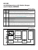
Pin Description
Block Diagram
PIN NAME FUNCTION
1 X1
2 X2
Connections for a Standard 32.768kHz Quartz Crystal. The internal oscillator circuitry is designed for
operation with a crystal having a specified load capacitance (C
L
) of 6.0pF. Pin X1 is the input to the
oscillator and can optionally be connected to an external 32.768kHz oscillator. The output of the internal
oscillator, pin X2, is left unconnected if an external oscillator is connected to pin X1.
3 V
BACKUP
Connection for a Secondary Power Supply. Supply voltage must be held between 1.3V and 5.5V for proper
operation. This pin can be connected to a primary cell, such as a lithium button cell. Additionally, this pin
can be connected to a rechargeable cell or a super cap when used with the trickle-charge feature. If not
used, this pin must be connected to ground. UL recognized to ensure against reverse charging current
when used with a lithium battery (www.maximintegrated.com/qa/info/ul/
).
4 GND Ground
5 SDA
Serial Data Output. SDA is the input/output for the I
2
C serial interface. This pin is open drain and requires
an external pullup resistor.
6 SCL
Serial Clock Input. SCL is the clock input for the I
2
C interface and is used to synchronize data movement
on the serial interface.
7 RST
Active-Low, Open-Drain Reset Output. This pin indicates the status of V
CC
relative to the V
PF
specification. As V
CC
falls below V
PF
, the RST pin is driven low. When V
CC
exceeds V
PF
, for t
RST
, the RST
pin is driven high impedance. The active-low, open-drain output is combined with a debounced
pushbutton input function. This pin can be activated by a pushbutton reset request. It has an internal
50k nominal value pullup resistor to V
CC
. No external pullup resistors should be connected. If the
crystal oscillator is disabled, the startup time of the oscillator is added to the t
RST
delay.
8 V
CC
DC Power Pin for Primary Power Supply
BLOCK 2BLOCK 1BLOCK 0
CLOCK AND CALENDAR
REGISTERS
POWER CONTROL
AND
TRICKLE CHARGER
I
2
C
INTERFACE
EEPROM
INTERFACE
EEPROM EEPROM
WATCHDOG
TIMER
STATUS CONTROL/
TRICKLE
X2
X1
V
CC
GND
V
BACKUP
RST
SDA
SCL
C
L
C
L
DS1388