
Datasheet


DS1374
I
2
C, 32-Bit Binary Counter Watchdog RTC with
Trickle Charger and Reset Input/Output
4 _____________________________________________________________________
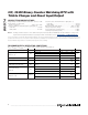
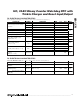
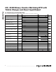
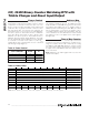
AC ELECTRICAL CHARACTERISTICS
(V
CC
= V
CC(MIN)
to V
CC(MAX)
, T
A
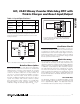
= -40°C to +85°C, unless otherwise noted.) (Note 2) (Figure 1)
PARAMETER SYMBOL CONDITIONS MIN TYP MAX UNITS
Fast mode 100 400
SCL Clock Frequency (Note 17) f
SCL
Standard mode 0 100
kHz
Fast mode 1.3
Bus Free Time Between STOP
and START Conditions
t
BUF
Standard mode 4.7
μs
Fast mode 0.6
Hold Time (Repeated) START
Condition (Note 18)
t
HD:STA
Standard mode 4.0
μs
Fast mode 1.3
Low Period of SCL Clock t
LOW
Standard mode 4.7
μs
Fast mode 0.6
High Period of SCL Clock t
HIGH
Standard mode 4.0
μs
Fast mode 0 0.9
Data Hold Time (Notes 19, 20) t
HD:DAT
Standard mode 0 0.9
μs
Fast mode 100
Data Setup Time (Note 21) t
SU:DAT
Standard mode 250
ns
Fast mode 0.6
Start Setup Time t
SU:STA
Standard mode 4.7
μs
Fast mode 300
Rise Time of Both SDA and SCL
Signals (Note 17)
t
R
Standard mode
20 +
0.1C
B
1000
ns
Fast mode 300
Fall Time of Both SDA and SCL
Signals (Note 17)
t
F
Standard mode
20 +
0.1C
B
300
ns
Fast mode 0.6
Setup Time for STOP Condition t
SU:STO
Standard mode 4.7
μs
Capacitive Load for Each Bus Line C
B
(Note 17) 400 pF
I/O Capacitance (SDA, SCL) C
I/O
(Note 22) 10 pF
Pulse Width of Spikes That Must
be Suppressed by the Input Filter
t
SP
Fast mode 30 ns
Pushbutton Debounce PB
DB
(Figure 2) 250 ms
Reset Active Time t
RST
(Figure 2) 250 ms
Oscillator Stop Flag (OSF) Delay t
OSF
(Note 23) 100 ms