
Datasheet


12 Maxim Integrated
Low-Current SPI/3-Wire RTCs
DS1343/DS1344
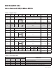
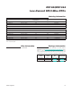
Table 1. Register Map
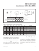
Table 2. Alarm Mask Bits
Note: Bits listed as 0 always read back as 0 and cannot be written to 1.
ADDRESS
BIT 7
MSB
BIT 6 BIT 5 BIT 4 BIT 3 BIT 2 BIT 1
BIT 0
LSB
FUNCTION RANGE
00h 0 10 Seconds Seconds Seconds 00–59
01h 0 10 Minutes Minutes Minutes 00–59
02h 0
12/24
AM/PM
10
Hours
Hour Hours
1–12 +
AM/PM
00–23
20
Hours
03h 0 0 0 0 0 Day Day 1–7
04h 0 0 10 Date Date Date 01–31
05h Century 0 0
10
Month
Month
Month/
Century
01–12 +
Century
06h 10 Year Year Year 00–99
07h A0M1 10 Seconds Seconds
Alarm 0
Seconds
00–59
08h A0M2 10 Minutes Minutes
Alarm 0
Minutes
00–59
09h A0M3
12/24
AM/PM
10
Hours
Hour Alarm 0 Hours
1–12 +
AM/PM
00–23
20
Hours
0Ah A0M4 0 0 0 Day Alarm 0 Day 1–7
0Bh A1M1 10 Seconds Seconds
Alarm 1
Seconds
00–59
0Ch A1M2 10 Minutes Minutes
Alarm 1
Minutes
00–59
0Dh A1M3
12/24
AM/PM
10
Hours
Hour Alarm 1 Hours
1–12 +
AM/PM
00–23
20
Hours
0Eh A1M4 0 0 0 Day Alarm 1 Day 1–7
0Fh
EOSC
X DOSF EGFIL SQW INTCN A1IE A0IE Control —
10h OSF 0 0 0 0 0 IRQF1 IRQF0 Status —
11h TCS3 TCS2 TCS1 TCS0 DS1 DS0 RS1 RS0
Trickle
Charger
—
12h–1Fh Reserved Reserved —
20h–7Fh User RAM User RAM 00h–FFh
ALARM REGISTER MASK BITS (BIT 7)
ALARM RATE
A_M4 A_M3 A_M2 A_M1
1 1 1 1 Alarm once a second
1 1 1 0 Alarm when seconds match
1 1 0 0 Alarm when minutes and seconds match
1 0 0 0 Alarm when hours, minutes, and seconds match
0 0 0 0 Alarm when day, hours, minutes, and seconds match