
Datasheet


15Maxim Integrated
Low-Current SPI/3-Wire RTCs
DS1343/DS1344
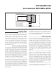
Assume, for the purposes of the example, that a system
power supply of 5V is applied to V
CC
and a super cap is
connected to V
BAT
. Also assume that the trickle charger
has been enabled with one diode and resistor R1. The
maximum current I
MAX
would be calculated as follows:
I
MAX
= (5.0V - diode drop)/R1 ≈ (5.0V - 0.6V)/2kΩ ≈
2.2mA
As the super cap charges, the voltage drop between
V
CC
and V
BAT
decreases, and therefore, the charge
current decreases.
Serial Port Operation
The devices offer the flexibility to choose between two
serial-interface modes. The component can commu-
nicate with the SPI interface or with a standard 3-wire
interface. The interface method used is determined by
SERMODE. When SERMODE is connected to V
CC
, SPI
communication is selected. When SERMODE is con-
nected to ground, standard 3-wire communication is
selected.
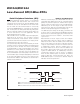
Figure 2. Trickle Charger Block Diagram
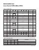
Table 3. Trickle-Charger Resistor and Diode Select
X = Don’t care.
R1
1k
Ω
R2
2k
Ω
R3
4k
Ω
V
CC
V
BAT
1 0F 18 SELECT
NOTE: ONLY 1010 CODE ENABLES CHARGER
1 OF 2
SELECT
1 OF 3
SELECT
TCS = TRICKLE-CHARGER SELECT
DS = DIODE SELECT
RS = RESISTOR SELECT
TRICKLE
CHARGER
REGISTER
TCS
BIT 7
TCS
BIT 6
TCS
BIT 5
TCS
BIT 4
DS
BIT 3
DS
BIT 2
RS
BIT 1
RS
BIT 0
TCS3 TCS2 TCS1 TCS0 DS1 DS0 RS1 RS0 FUNCTION
X X X X X X 0 0 Disabled
X X X X 0 0 X X Disabled
X X X X 1 1 X X Disabled
1 0 1 0 0 1 0 1
No diode, 1kI
1 0 1 0 0 1 1 0
No diode, 2kI
1 0 1 0 0 1 1 1
No diode, 4kI
1 0 1 0 1 0 0 1
One diode, 1kI
1 0 1 0 1 0 1 0
One diode, 2kI
1 0 1 0 1 0 1 1
One diode, 4kI
0 0 0 0 0 0 0 0 Initial power-on state—disabled