
Datasheet

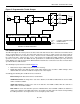


DS1339 I
2
C Serial Real-Time Clock
11 of 20
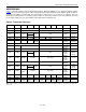
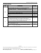
ADDRESS MAP
Table 3 shows the address map for the DS1339 registers. During a multibyte access, when the address pointer
reaches the end of the register space (10h), it wraps around to location 00h. On an I
2
C START, STOP, or address
pointer incrementing to location 00h, the current time is transferred to a second set of registers. The time
information is read from these secondary registers, while the clock may continue to run. This eliminates the need
to re-read the registers in case of an update of the main registers during a read.
Table 3. Timekeeper Registers
ADDRESS BIT 7 BIT 6 BIT 5 BIT 4 BIT 3 BIT 2 BIT 1 BIT 0 FUNCTION RANGE
00h 0 10 Seconds Seconds Seconds 00–59
01h 0 10 Minutes Minutes Minutes 00–59
02h 0 12/24
AM/PM
10 Hour Hour Hours
1–12
+AM/PM
00–23
20 Hour
03h
0
0
0
0
0
Day
Day
1–7
04h
0
0
10 Date
Date
Date
01–31
05h Century 0 0
10
Month
Month
Month/
Century
01–12 +
Century
06h 10 Year Year Year 00–99
07h A1M1 10 Seconds Seconds
Alarm 1
Seconds
00–59
08h A1M2 10 Minutes Minutes
Alarm 1
Minutes
00–59
09h A1M3 12/24
AM/PM
10 Hour Hour
Alarm 1
Hours
1–12 +
AM/PM
00–23
20 Hour
0Ah A1M4 DY/DT 10 Date Day, Date
Alarm 1
Day,
Alarm 1
Date
1-7, 1-31
0Bh A2M2 10 Minutes Minutes
Alarm 2
Minutes
00–59
0Ch A2M3
12/24
AM/PM
10 Hour Hour
Alarm 2
Hours
1–12 +
AM/PM
00–23
20 Hour
0Dh A2M4
DY/DT
10 Date Day, Date
Alarm 2
Day,
Alarm 2
Date
1–7, 1–31
0Eh
EOSC
0 BBSQI RS2 RS1 INTCN A2IE A1IE Control —
0Fh OSF 0 0 0 0 0 A2F A1F Status —
10h TCS3 TCS2 TCS1 TCS0 DS1 DS0
ROUT1 ROUT0
Trickle
Charger
—
Note: Unless otherwise specified, the state of the registers are not defined when power is first applied or when V
CC
and V
BACKUP
falls below the
V
BACKUP(MIN)
.