
Datasheet

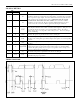
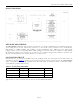


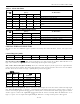
Table Of Contents

DS1337 I
2
C Serial Real-Time Clock
BLOCK DIAGRAM
DETAILED DESCRIPTION
The Block Diagram shows the main elements of the DS1337. As shown, communications to and from the DS1337
occur serially over an I
2
C bus. The DS1337 operates as a slave device on the serial bus. Access is obtained by
implementing a START condition and providing a device identification code, followed by data. Subsequent
registers can be accessed sequentially until a STOP condition is executed. The device is fully accessible through
the I
2
C interface whenever V
CC
is between 5.5V and 1.8V. I
2
C operation is not guaranteed when V
CC
is below 1.8V.
The DS1337 maintains the time and date when V
CC
is as low as 1.3V.
OSCILLATOR CIRCUIT
The DS1337 uses an external 32.768kHz crystal. The oscillator circuit does not require any external resistors or
capacitors to operate. Table 1
specifies several crystal parameters for the external crystal. The Block Diagram
shows a functional schematic of the oscillator circuit. The startup time is usually less than 1 second when using a
crystal with the specified characteristics.
Table 1. Crystal Specifications*
PARAMETER SYMBOL MIN TYP MAX UNITS
Nominal Frequency f
O
32.768 kHz
Series Resistance ESR 50
kΩ
Load Capacitance C
L
6 pF
*The crystal, traces, and crystal input pins should be isolated from RF generating signals. Refer to
Application Note 58: Crystal Considerations for Dallas Real-Time Clocks for additional specifications.
6 of 16