
Datasheet
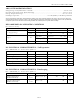
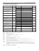


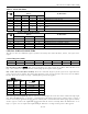
Table Of Contents

DS1337 I
2
C Serial Real-Time Clock
Table 3. Alarm Mask Bits
DY/
DT
ALARM 1 REGISTER MASK BITS
(BIT 7)
ALARM RATE
A1M4
A1M3
A1M2
A1M1
X
1
1
1
1
Alarm once per second
X
1
1
1
0
Alarm when seconds match
X
1
1
0
0
Alarm when minutes and seconds match
X
1
0
0
0
Alarm when hours, minutes, and seconds match
0 0 0 0 0
Alarm when date, hours, minutes, and seconds
match
1
0
0
0
0
Alarm when day, hours, minutes, and seconds match
DY/
DT
ALARM 2 REGISTER MASK BITS
(BIT 7)
ALARM RATE
A2M4
A2M3
A2M2
X
1
1
1
Alarm once per minute (00 seconds of every minute)
X
1
1
0
Alarm when minutes match
X
1
0
0
Alarm when hours and minutes match
0
0
0
0
Alarm when date, hours, and minutes match
1
0
0
0
Alarm when day, hours, and minutes match
SPECIAL-PURPOSE REGISTERS
The DS1337 has two additional registers (control and status) that control the RTC, alarms, and square-wave
output.
Control Register (0Eh)
Bit 7 Bit 6 Bit 5 Bit 4 Bit 3 Bit 2 Bit 1 Bit 0
EOSC
0 0 RS2 RS1 INTCN A2IE A1IE
Bit 7:
Enable Oscillator
(EOSC
). This active-low bit when set to logic 0 starts the oscillator. When this bit is set to
logic 1, the oscillator is stopped. This bit is enabled (logic 0) when power is first applied.
Bits 4 and 3: Rate Select (RS2 and RS1). These bits control the frequency of the square-wave output when the
square wave has been enabled. The table below shows the square-wave frequencies that can be selected with the
RS bits. These bits are both set to logic 1 (32kHz) when power is first applied.
SQW/
INTB
Output
INTCN
RS2 RS1
SQW/
INTB
OUTPUT
A2IE
0
0
0
1Hz
X
0
0
1
4.096kHz
X
0
1
0
8.192kHz
X
0
1
1
32.768kHz
X
1
X
X
A2F
1
Bit 2: Interrupt Control (INTCN). This bit controls the relationship between the two alarms and the interrupt output
pins. When the INTCN bit is set to logic 1, a match between the timekeeping registers and the alarm 1 registers l
activates the INTA pin (provided that the alarm is enabled) and a match between the timekeeping registers and the
alarm 2 registers activates the SQW/INTB pin (provided that the alarm is enabled). When the INTCN bit is set to
logic 0, a square wave is output on the SQW/INTB pin. This bit is set to logic 0 when power is first applied.
10 of 16