
Datasheet


DS1307 64 x 8, Serial, I
2
C Real-Time Clock
9 of 15
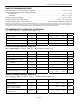
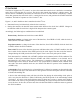
CONTROL REGISTER
The DS1307 control register is used to control the operation of the SQW/OUT pin.
BIT 7 BIT 6 BIT 5 BIT 4 BIT 3 BIT 2 BIT 1 BIT 0
OUT 0 0 SQWE 0 0 RS1 RS0
Bit 7: Output Control (OUT). This bit controls the output level of the SQW/OUT pin when the square-
wave output is disabled. If SQWE = 0, the logic level on the SQW/OUT pin is 1 if OUT = 1 and is 0 if
OUT = 0.
Bit 4: Square-Wave Enable (SQWE). This bit, when set to logic 1, enables the oscillator output. The
frequency of the square-wave output depends upon the value of the RS0 and RS1 bits. With the square-
wave output set to 1Hz, the clock registers update on the falling edge of the square wave.
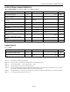
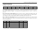
Bits 1, 0: Rate Select (RS1, RS0). These bits control the frequency of the square-wave output when the
square-wave output has been enabled. The following table lists the square-wave frequencies that can be
selected with the RS bits.
RS1 RS0 SQW/OUT OUTPUT SQWE OUT
0 0 1Hz 1 X
0 1 4.096kHz 1 X
1 0 8.192kHz 1 X
1 1 32.768kHz 1 X
X X 0 0 0
X X 1 0 1