
Datasheet


DS1307 64 x 8, Serial, I
2
C Real-Time Clock
11 of 15
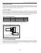
Figure 3. Data Transfer on I
2
C Serial Bus
Depending upon the state of the R/W bit, two types of data transfer are possible:
1. Data transfer from a master transmitter to a slave receiver. The first byte transmitted by the
master is the slave address. Next follows a number of data bytes. The slave returns an acknowledge
bit after each received byte. Data is transferred with the most significant bit (MSB) first.
2. Data transfer from a slave transmitter to a master receiver. The first byte (the slave address) is
transmitted by the master. The slave then returns an acknowledge bit. This is followed by the slave
transmitting a number of data bytes. The master returns an acknowledge bit after all received bytes
other than the last byte. At the end of the last received byte, a “not acknowledge” is returned.
The master device generates all the serial clock pulses and the START and STOP conditions. A
transfer is ended with a STOP condition or with a repeated START condition. Since a repeated
START condition is also the beginning of the next serial transfer, the bus will not be released. Data is
transferred with the most significant bit (MSB) first.
A
CKNOWLEDGEMENT
SIGNAL FROM RECEIVER
A
CKNOWLEDGEMENT
SIGNAL FROM RECEIVER
R/
W
DIRECTION
BIT
REPEATED IF MORE BYTES
A
RE TRANSFERED
START
CONDITION
STOP
CONDITION
OR
REPEATED
START
CONDITION
MSB
1 2 6 7 8 9 1 2 3-7 8 9
A
CK
A
CK
SDA
SCL