
Datasheet


DS1307 64 x 8, Serial, I
2
C Real-Time Clock
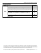
REVISION HISTORY
REVISION
DATE
DESCRIPTION
PAGES
CHANGED
100208
Moved the Typical Operating Circuit and Pin Configurations to first page.
1
Removed the leaded part numbers from the Ordering Information table.
1
Added an open-drain transistor to SQW/OUT in the block diagram (Figure 1).
4
Added the pullup voltage range for SDA, SCL, and SQW/OUT to the Pin
Description table and noted that SQW/OUT can be left open if not used.
6
Added default time and date values on first application of power to the Clock
and Calendar section and deleted the note that initial power-on state is not
defined.
8
Added default on initial application of power to bit info in the Control Register
section.
9
Updated the Package Information section to reflect new package outline
drawing numbers.
13
Maxim Integrated cannot assume responsibility for use of any circuitry other than circuitry entirely embodied in a Maxim Integrated product. No circuit patent licenses
DUHLPSOLHG0D[LP,QWHJUDWHGUHVHUYHVWKHULJKWWRFKDQJHWKHFLUFXLWU\DQGVSHFL¿FDWLRQVZLWKRXWQRWLFHDWDQ\WLPH7KHSDUDPHWULFYDOXHVPLQDQGPD[OLPLWV
VKRZQLQWKH(OHFWULFDO&KDUDFWHULVWLFVWDEOHDUHJXDUDQWHHGOther parametric values quoted in this data sheet are provided for guidance.
Maxim Integrated and the Maxim Integrated logo are trademarks of Maxim Integrated Products, Inc.
©
2008 Maxim Integrated Products, Inc.
Ň
14
For pricing, delivery, and ordering information, please contact Maxim Direct at 1-888-629-4642, or visit Maxim Integrated’s website at www.maximintegrated.com.