
Datasheet


DS1251/DS1251P
6 of 20
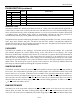
PHANTOM CLOCK REGISTER DEFINITION Figure 2
AM/PM/12/24 MODE
Bit 7 of the hours register is defined as the 12-hour or 24-hour mode-select bit. When high, the 12-hour
mode is selected. In the 12-hour mode, bit 5 is the AM/PM bit with logic high being PM. In the 24-hour
mode, bit 5 is the 20-hour bit (20–23 hours).
OSCILLATOR AND RESET BITS
Bits 4 and 5 of the day register are used to control the
RST
and oscillator functions. Bit 4 controls the
RST
(pin 1). When the
RST
bit is set to logic 1, the
RST
input pin is ignored. When the
RST
bit is set to
logic 0, a low input on the
RST
pin will cause the phantom clock to abort data transfer without changing
data in the watch registers. Bit 5 controls the oscillator. When set to logic 1, the oscillator is off. When set
to logic 0, the oscillator turns on and the watch becomes operational. These bits are shipped from the
factory set to a logic 1.
ZERO BITS
Registers 1, 2, 3, 4, 5, and 6 contain one or more bits, which will always read logic 0. When writing these
locations, either a logic 1 or 0 is acceptable.