
Datasheet


DS1251/DS1251P
18 of 20
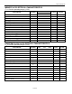
AC TEST CONDITIONS
Output Load: 50pF + 1TTL Gate
Input Pulse Levels: 0 to 3V
Timing Measurement Reference Levels
Input: 1.5V
Output: 1.5V
Input Pulse Rise and Fall Times: 5ns
NOTES:
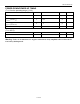
1) WE is high for a read cycle.
2) OE = V
IH
or V
IL
. If OE = V
IH
during write cycle, the output buffers remain in a high-impedance state.
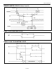
3) t
WP
is specified as the logical AND of CE and WE. t
WP
is measured from the latter of CE or WE going
low to the earlier of CE or WE going high.
4) t
DH
, t
DS
are measured from the earlier of CE or WE going high.
5) These parameters are sampled with a 50pF load and are not 100% tested.
6) If the CE low transition occurs simultaneously with or later than the WE low transition in Write Cycle
1, the output buffers remain in a high-impedance state during this period.
7) If the CE high transition occurs prior to or simultaneously with the WE high transition, the output
buffers remain in a high-impedance state during this period.
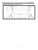
8) If WE is low or the WE low transition occurs prior to or simultaneously with the CE low transition,
the output buffers remain in a high impedance state during this period.
9) The expected t
DR
is defined as cumulative time in the absence of V
CC
with the clock oscillator
running.
10) t
WR
is a function of the latter occurring edge of WE or CE.
11) Voltages are referenced to ground.
12) RST (Pin 1) has an internal pullup resistor.
13) Real-time clock modules can be successfully processed through conventional wave-soldering
techniques as long as temperature exposure to the lithium energy source contained within does not
exceed +85°C. Post-solder cleaning with water-washing techniques is acceptable, provided that
ultrasonic vibration is not used.
In addition, for the PowerCap:
1) Maxim recommends that PowerCap Module bases experience one pass through solder reflow oriented
with the label side up (“live-bug”).
2) Hand soldering and touch-up: Do not touch or apply the soldering iron to leads for more than three
seconds.
− To solder, apply flux to the pad, heat the lead frame pad, and apply solder. To remove the part,
apply flux, heat the lead frame pad until the solder reflows, and use a solder wick to remove
solder.