
Design Guidelines Instruction Manual


78M6610+PSU Hardware Design Guidelines AN_6610_107
8 Rev 0
3.1 Current Transformer Selection
The consideration for selecting a current transformer should include measurement accuracy, line
frequency (and harmonics), current range and the CT’s turns ratio. The load current range should also be
considered. Subjecting a current transformer to load currents above the manufacturer’s rated current
specification may saturate the CT and cause winding failures due to excessive temperature rise. On the
other hand, a current transformer that is rated much higher than the target load current might be
restrictively too large and expensive for its purpose.
I Load
I Secondary
AIN
AIP
750
V
3P3A
750
100n
100n
1000p
1000p
RBurden
CT
78M6610+PSU
10K
10K
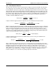
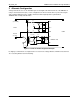
Figure 4: Current Transformer (CT) Basic Connections
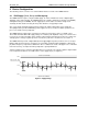
Usually, current transformers have turns ratios ranging from 10:1 to 2500:1. The higher the turns ratio
(TurnRatio = Nsecondary/Nprimary), the higher the resolution of the current measurement. A too high
turns ratio increases distributed capacitance and leakage inductance. These characteristics may
decrease the CT’s accuracy and capability to operate at higher frequencies. However, if the number of
turns is too low, the output signal may distort or “droop” (for positively sloped unipolar input signals). Such
distortion may cause measurement inaccuracies. We recommend a minimum turns ratio of 1000:1.
The next step towards selecting a current transformer is the calculation of the burden resistor’s value
(RBurden). The 78M6610+PSU signal input range is ±176.78 mVrms (±250 mVpk). Therefore, the CT’s
secondary output voltage (Vout) must operate within this range. Assuming the maximum load current is
20 Arms (28.284A pk), a 1000:1 ratio current transformer will produce a secondary current of 20 mA rms
(28.284 mA pk). Per Figure 4, the burden resistor’s value is calculated as follows:
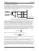
=
Using the values in the above example, the value of the burden resistor is:
=
0.250
0.028284
= 8.85
A standard value 8.2 Ω resistor is recommended. Always consult the CT’s manufacturer for proper usage
of their CT and burden resistor recommendations.
The use of a CT allows for the 78M6610+PSU’s V
3P3
to be isolated from the plant NEUTRAL wiring. This
topology eliminates the safety issues stated earlier regarding shunt-based current sensing.
The V
3P3
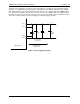
reference point critical to multi-shunt measurement performance is not an issue with CTs. The
output currents generated by the CT’s secondary winding is small enough that the sheet resistance of the
1 oz. copper plating does not present measurement errors from adjacent CTs. Shield the CTs secondary
pins, burden resistor and filter components with top and bottom printed circuit board layer V
3P3
plane
surfaces. Insert multiple V
3P3
vias to interconnect the top and bottom V
3P3
structures for a low impedance
shield.