
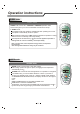
Operation Manual
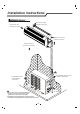


Installation instructions
Indoor unit Indoor unit
HEAT PUMP
HEAT PUMP
HEAT PUMP
HEAT PUMP
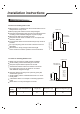
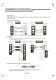
7K,9K,12K,18K,22K Model
Wiring Diagram
Make sure that the color of wires of the outdoor unit and the terminal No. are the same as those
of the indoor unit.
24K Model
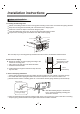
Defrost Cable (for heat pump air conditioner only)
Outdoor unit Outdoor unit
Power connecting cord
Power connecting cord
Power connecting cord I
Blue
Blue
Blue
Blue
Blue
Blue
Yellow/Green
Yellow/Green
Yellow/Green
Yellow/Green
Brown
Brown
Brown
Brown
Brown
Brown
NN
2L
NN
2L
1L
1L
1L
1L
3L 3L
COOLING ONLY
COOLING ONLY
Defrost wire (indoor)
Defrost wire(outdoor)
Indoor unit
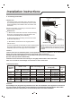
For 24K model, the power supply are connected from outdoor unit, with a circuit breaker.
Other models from indoor unit.)
For above models, the power supply are connected from indoor unit, with a plug.
After connection, the defrost wire should be well wrapped with a wrapping tape and the
the connector should be put inside the unit.
Indoor unit
Outdoor unit Outdoor unit
Terminal Terminal Terminal Terminal
TerminalTerminalTerminalTerminal
Terminal
Terminal
N
L
1L 1L
3L 3L
2L 2L
N
N
L
L
Power connecting cord I
Power connecting cord
Power connecting cord
Blue
Blue
Blue
Blue
Yellow/Green
Yellow/Green
Yellow/Green
Yellow/Green
Power supply
Power supply
Black
Black
Violet
Violet
Orange
Orange
Orange
Brown
Brown
Brown
Brown
Orange
N
L
1L
1L
N
L
N
L
Defrost cable(for heat-pump models only)
20