
Installation Instructions


28
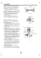
AIRPURGING
Whenrelocatetheunittoanotherplace,
performevacuationusingvacuumpump.
Makesuretherefrigerantaddedintotheair
conditionerisliquidforminanycase.
(NotapplicabletotheunitsadoptfreonR22)
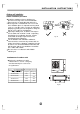
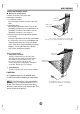
Openthevalvestemuntilithitsagainstthe
stopper.Donottrytoopenitfurther.
Securelytightenthevalvestemcapwitha
spannerorthelike.
Valvestemcaptighteningtorque(See
Tighteningtorquetableinpreviouspage).
Outdoor
unit
Indoor
unit
Refrigerant
Flarenut
Stopper
Cap
Valvebody
Packedvalve Halfunion
Gasside
Liquidside
A
C
D
B
Valvestem
Fig.56
Fig.57
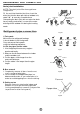
WhenUsingtheVacuumPump
(Formethodofusingamanifoldvalve,refer
toitsoperationmanual.)
1.Completelytightentheflarenuts,A,B,C,D,
valvechargehosetoa
chargeportofthelow-pressurevalveonthe
gaspipeside.
2.Connectthechargehoseconnectiontothe
vacuumpump.
3.FullyopenthehandleLoofthemanifoldvalve.
4.Operatethevacuumpumptoevacuate.After
slightlyloosetheflarenut
oftheLovalveonthegaspipeside
checkthattheairisentering(Operationnoise
pumpchangesanda
commeterindicates0insteadofminus)
5.Aftertheevacuationiscomplete,fullyclose
manifoldvalveandstop
theoperationofthevacuumpump.Make
evacuationfor15minutesormore
compoundmeterindicates
-76cmHg(-1x10Pa).
6.TurnthestemofthepackedvalveBabout
45counterclockwisefor6~7secondsafter
thegascomingout,thentightentheflarenut
again.Makesurethepressuredisplayinthe
pressureindicatorisalittlehigherthanthe
atmospherepressure.
7.RemovethechargehosefromtheLow
pressurechargehose.
8.FullyopenthepackedvalvestemsBandA.
9.Securelytightenthecapofthepackedvalve.
connectthemanifold
startingevacuation,
and
ofthevacuum
pound
thehandleLoofthe
andcheck
thatthe
5
o
Manifoldvalve
Compoundmeter
-76cmHg
HandleLo
HandleHi
Chargehose
Chargehose
Vacuumpump
Pressuregauge
Lowpressurevalve
Fig.58
Cautioninhandlingthepackedvalve