
Installation Instructions


26
ELECTRICALWORK
Fig.53
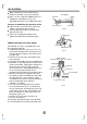
Connectthecabletotheoutdoorunit
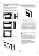
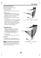
1.Removetheelectricalcontrolboardcover
fromtheoutdoorunitbylooseningthescrew
asshowninFig.51.
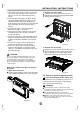
2.Connecttheconnectivecablestothe
terminalsasidentifiedwiththeirrespective
matchednumbersontheterminalblockof
indoorandoutdoorunits.
3.Securethecableontothecontrolboardwith
thecordclamp.
4.Topreventtheingressofwater,fromaloop
oftheconnectivecableasillustratedinthe
installationdiagramofindoorandoutdoor
units.
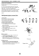
5.Insulateunusedcords(conductors)with
PVC-tape.Processthemsotheydonot
touchanyelectricalormetalparts.
Wiringconnection
NOTE:Beforeperforminganyelectrical
work,turnoffthemainpowertothesystem.
ConnectionCable
10mm
40mm
Fig.55
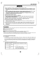
CAUTIONS
Donottouchthecapacitorevenifyou
havedisconnectedthepowerforthereis
stillhighvoltagepoweronit,orelectric
shockhazardmayoccur.Foryoursafety,
youshouldstartrepairingatleast5minutes
laterafterthepowerisdisconnected.
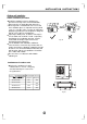
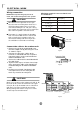
ThepowerissuppliedfromtheOutdoor
Unit.ThefourIndoorUnitareconnected
withasignalwiresorpowercordsare
connectedreliablyandcorrectly,orthe
airconditionercouldnotrunnormally.
One-two One-three One-four
One-five
Fig.54
CAUTIONS
Makesuretoconnecttheindoorunit(A,B,C,D)
totheHiandLovalveandterminalsofsignal
wires(A,B,C,D)ofoutdoorunitasidentified
withtheirrespectivematchedconnection.
Wrongwiringconnectionsmaycausesome
electricalpartstomalfunction.
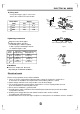
Minimumnorminalcross-sectionalarea
ofconductors:
Ratedcurrentofappliance
(A)
Nominalcross-sectional
area(mm)
2
>3and<6
>6and<10
>10and<16
>16and<25
0.75
1
1.5
2.5
POWER
Screw
Cover
E
E
L(A)N(A)S(A)
LNS
L(B)N(B)S(B)
LNS
L(C)N(C)S(C)
LNS
L(D)N(D)S(D)
LNS
L(E)N(E)S(E)
LNS