
Installation Instructions


14
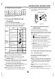
INSTALLATIONINSTRUCTIONS
Air-ingrille Airinlet
Fig.34a
Fig.33
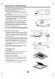
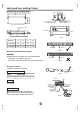
Thepositionofhangingbolts
25
C
D
Airoutlet(onside)
Airoutletsketchmap
380
220
175
Wateroutlet
,
Φ
25
Refrigerantpipingjoint
gasside
()
A
B
Freshairinlet
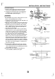
Ceiling
>500mm
>500mm
148
A
B
Φ100
Refrigerantpipingjoint
(gasside)
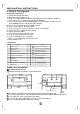
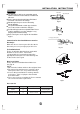
Air-ingrille
Airinlet
Fig.34b
AirInletPanelofAirReturnBox
Maketheairinletgrilleandairinletdirection
inparallelasshowninFig.34a.
Fig.34bisincorrect,whichmaycauseloudnoise.
CAUTION
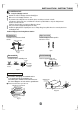
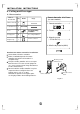
Drainpipeinstallation
Piping,insulationmaterial
Drainage
Heatinsulation
Piping
Insulationmaterial
HardPVCpipe
Cellularpolyethylene,thickerthan6mm
Pleasedoheatinsulationonpipingjoint.
Bindthecontactinsulationpartbetweenthe
unitandinstallationlocationwithbandage.
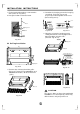
1. Indoorunitdrainpipeinstallation
Fig.35
Fig.36
HardPVCpipe
Heatinsulation
material
Heatinsulation
material
Nospace
Mainunit
Sealthe
insulationmaterial
SeeFig.35.
MODEL
<12000Btu/h
>12000Btu/h
A B C D
915
1260
870
1224
715
1015
870
1215