
Installation Instructions

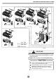


2.Four-waycassettetype
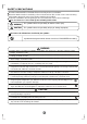
1.Decidethecorrectcarry-inpath.
2.Movethisunitasoriginallypackagedaspossible.
3.Iftheairconditionerisinstalledonametalpart
ofthebuilding,itmustbeelectricallyinsulated
accordingtotherelevantelectricalcode.
4.Ifinstallinginalonelybuildingoratahighposition
whereitishotandhumidwithfrequentthunder-
storm,lightning-protectionequipmentisnecessary.
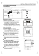
Notesbeforeinstallation
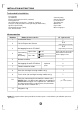
1.Installthemainbody
A.Theexistingceiling(tobehorizontal)
a.Pleasecutaquadrangularholeof600600mm
intheceilingaccordingtotheshapeofthe
installationpaperboard.(RefertoFig.15&16)
Thecenteroftheholeshouldbeatthesame
positionofthatoftheairconditionerbody.
Determinethelengthsandoutletsoftheconn-
ectingpipe,drainpipeandcables.
Tobalancetheceilingandtoavoidvibration,
pleaseenforcetheceilingwhennecessary.
b.Pleaseselectthepositionofinstallationhooks
accordingtothehookholesontheinstallation
board.
Drillfourholesof12mm,50~55mmdeepatthe
selectedpositionsontheceiling.Thenembed
theexpansiblehooks(fittings).
Facetheconcavesideoftheinstallationhooks
towardtheexpansiblehooks.Determinethe
lengthoftheinstallationhooksfromtheheight
ofceiling,thencutofftheunnecessarypart.
Iftheceilingisextremelyhigh,pleasedetermine
thelengthoftheinstallationhookaccordingto
facts.
Cuttheinstallationhookopeninthemiddle
position,thenuseapropriatelengthofreinforcing
rod(12)toweldtogether.
×
Indoorunitinstallation
9
INSTALLATIONINSTRUCTIONS
Pleasecheckwhetherthefollowingfittingsareoffullscope.Iftherearesomeattachedfittingsfree
fromuse,pleaserestorethemcarefully.
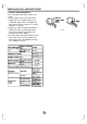
InstallationFittings
Tubing&Fittings
1.Expansiblehook.................................4
2.Installationhook.................................4
3.Installationpaperboard.....................1
4.BoltM612.....................4
×
M516or
×
Attachedfittings
6
.Connectingpipegroup.........................1
8.Soundproof/insulationsheath.............2
7.Bindingtape.........................................6
Remotecontroller&ItsFrame
9.Remotecontroller...........................1
10.Frame.............................................1
11.Mountingscrew(ST2.910-C-H)...2
×
12.Alkalinedrybatteries(AM4)............2
5.Magneticring..........................................1
Fig.13
Fig.14
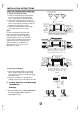
Ground
OutletOutlet Inlet
>1000
>1000
Fig.15
Drainside
A
422 28.5
611(Hooklocation)
580(Body)
600(Ceilinghole)
650(Panel)
(onsomemodels)