
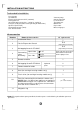
Installation Instructions

6
INSTALLATIONINSTRUCTIONS
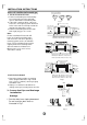
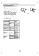
Fig.4
Correctorientation
ofInstallationPlate
Wall
Indoor
Outdoor
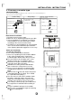
Fig.6
Fig.5
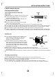
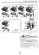
Indoorunitinstallation(wall-mountedtype)
2.Drillaholeinthewall
Note:
1.FittheInstallationPlate
1.Fittheinstallationplatehorizontally
onstructuralpartsofthewallwith
spacesaroundtheinstallationplate.
2.Ifthewallismadeofbrick,concrete
orthelike,drilleight(8)5mmdiameter
holesinthewall.InsertClipanchorfor
appropriatemountingscrews.
3.Fittheinstallationplateonthewall
witheight(8)type “A” screws.
FittheInstallationPlateanddrill
holesinthewallaccordingtothe
wallstructureandcorresponding
mountingpointsontheinstallation
plate.TheInstallationPlatemaybe
slightlydifferentaccordingtothe
differentmodelsofindoorunit.
(Dimensionsarein “mm” unless
otherwisestated)
1.Determineholepositionsaccording
tothediagramdetailedinFig.5.Drill
one(1)hole(65mm)slantingslightly
tooutdoorside.
2.Alwaysusewallholeconduitwhen
drillingmetalgrid,metalplateorthelike.
φ
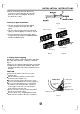
3.ConnectivePipeandDrainage
Installation
1.Runthedrainhoseslopingdownward.
Donotinstallthedrainhoseas
illustratedinFig.7.
Drainage
Fig.7
Donotblockwaterflowbyarise.
Donotputtheendof
drainhoseintowater.
150mmormoretoceiling
Indoorunitoutline
Installationplate
Rightrearside
refrigerant
pipehole65
φ
Leftrearside
refrigerant
pipehole65
φ
120mmor
moretowall
120mmor
moretowall
918
190
150
A
Rightrearside
refrigerant
pipehole65
φ
Installationplate
Indoorunitoutline
Leftrearside
refrigerant
pipehole65
φ
150mmormoretoceiling
120mmor
moretowall
120mmor
moretowall
ModelA(A:710,B:250,C:100,D:110)
ModelA(A:710,B:250,C:100,D:110)
ModelA(A:920,B:293,C:150,D:185)
ModelB()A:790,B:265,C:100,D:150
ModelB()A:790,B:275,C:100,D:85
ModelC()A:850,B:290,C:100,D:115
ModelB()A:995,B:293,C:150,D:200
ModelC()A:850,B:305,C:150,D:145
C
D