
Instruction manual


/
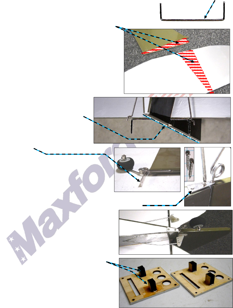
4. Tail Surfaces –
a. Test-fit the vertical stabilizer, rudder, horizontal stabilizer and both elevator halves to the fuselage. If
necessary, cut through any Mylar covering the precut CA-hinge slots. (NOTE: Position the metal joiner
in the horizontal stabilizer’s slot before sliding the horizontal
stabilizer into its slot.)
b. Ensure good wood-to-wood glue joints by trimming and removing
the horizontal and vertical stabilizer’s Mylar covering that will be
‘burried’ inside the mounting slots in the fuselage.
c. Slide the elevator’s metal joiner and the horizontal
stabilizer into the horizontal slot at the end of the
fuselage. Center and align the horizontal stab. at a
right angle to the centerline of the fuselage, and
secure it in place with epoxy.
d. Use epoxy to secure the elevator’s metal joiner into
each half of the elevator; then, before the epoxy
cures, use thin CA and the supplied CA hinges to
attach each half of the elevator to the horizontal
stabilizer.
e. Secure the vertical stabilizer into its
slot in the fuselage with epoxy. Ensure
the aft portion of the vertical stabilizer
aligns with the end of the fuselage.
f. Use a wheel collar to attach the tail
wheel to its strut.
g. Position the tail wheel strut’s
mounting base onto the tail wheel’s
strut.
h. Test fit the tail wheel’s strut into its groove
and the opening in the base of the rudder.
(NOTE: It may be necessary to remove excess
Mylar from the leading edge of the rudder.)
i. Use epoxy to secure the tail wheel strut into the
rudder.
j. Attach the rudder to the vertictal stabilizer with CA hinges and thin CA.
k. Use two 5/16-inch wood screws to attach the tail wheel strut’s
mounting base to the bottom of the fuselage.
l. Twist control horns onto the elevator’s and the
rudder’s pushrods; use the supplied bolts and
control horn backplates to secure one control
horns to the rudder and the other to the elevator.
6. Aileron Servos and Ailerons –
a. Test fit your aileron servos and prepare the aileron
servo mounts by using epoxy to attach two servo-
mounting pedestals to each servo hatch cover.
b. Test-fit the ailerons to their wing panels, control
horns and pushrods. (NOTE: Small holes in the
Mylar show where to mount the aileron control
horns; if necessary, you may reposition the aileron
control horns to fit your servos; you might also
need to slice through any Mylar that covers the
precut CA-hinge slots.)
(
1/4
-
inch
squares)
Page 7 of 14
S121015 Copyright 2012
(
Bottom side of the
Horizontal Stab.)
(Vert. Stab.)
NOTE:
Protect the wood by
using
the
hot tip of a soldering iron to trim
the Mylar; do NOT use a knife-blade.