
Instruction manual


/
radio receiver’s throttle channel; switch ON your transmitter and set transmitter’s throttle and throttle
trim controls to minimum; with no propeller on the motor, switch ON your transmitter and connect
the ESC to the battery; after you hear a series of initialization sounds, slowly raise the transmitter’s
throttle to no more than 25% of maximum.
d) Carefully run the motor slowly and only for the few seconds necessary to observe its direction of
rotation. If the motor rotated in the clockwise (correct) direction as viewed from the rear of the
airplane, return the throttle to minimum, disconnect the ESC from the battery, switch OFF the
transmitter, and set your battery and transmitter aside. If the motor powered up in
the counterclockwise (wrong) direction, return the throttle control to minimum,
disconnect the ESC from the battery, swap either two of the three ESC-to-motor
wires, and repeat the above procedure to ensure the motor rotates in the correct
direction.
j. If you are installing the optional dummy engine, use epoxy and/or wood screws to
attach the mounting plates 1 3/4-inch above the bottom edges and close the side edge
of the cowl.
k. Position the cowl so the propeller backplate protrudes approx. 1/4 inch beyond the
face of the cowl; use low-tack masking tape to temporarily hold the cowl in position;
use the provided 5/16-inch screws to attach the cowl; and remove the masking tape.
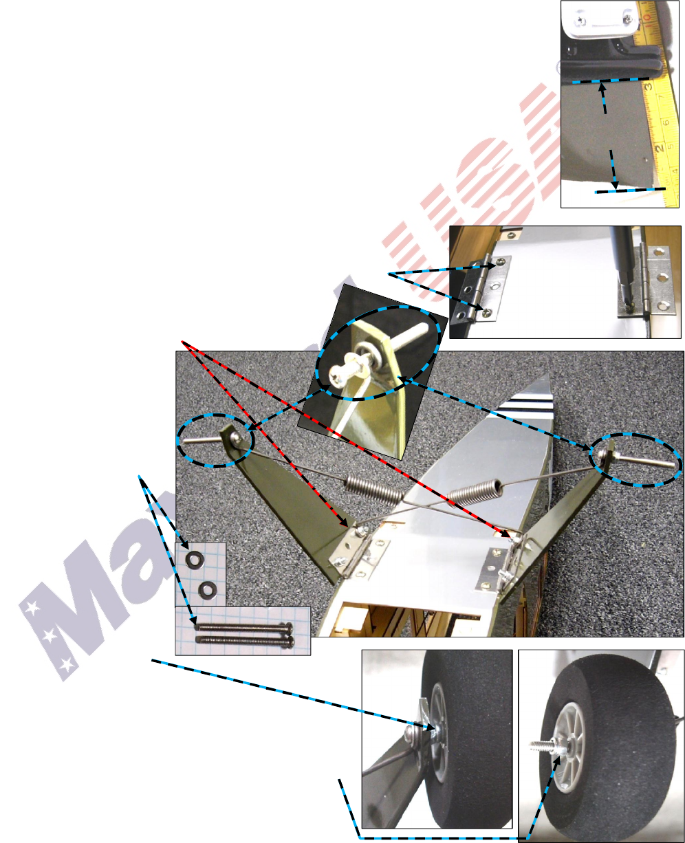
3. Main Landing Gear –
(NOTE: If you are using floats, replace this section with the detailed
instructions included with the floats.)
a. As shown at the right, turn the fuselage upside down and attach the
hinges by driving two bolts into the preinstalled blind nuts.
b. Use two bolts and self-locking nuts to attach each
landing gear strut to its hinge. Place one end of an
8-inch long spring under the two rearmost self-
locking nuts.
c. If necessary, bend the
spring’s ends so the
straight portion of the
spring ‘points’ toward
the opposing axle.
d. Place flat washers
on two 1 1/2-inch
long bolts. Insert a
bolt through the free
end of each spring,
guide the bolts into
and through the holes
in the ends of the
main gear struts.
e. Use a self-locking nut
to secure the bolts and
springs to the struts.
f. Place a wheel onto the
end of each 1 1/2-inch long bolt
and use a self-locking nut to hold each wheel
onto its axle.
g. Apply a drop of CA adhesive to ensure each wheel is
secured to its axle. (You may also choose to use a
rotary tool with a cutting wheel to remove and
discard the excess length of each bolt/axle.)
Page 6 of 14
S121015 Copyright 2012
Approx.
1 3/4 inch
(
1/4
-
inch squares)