
Instruction manual


/
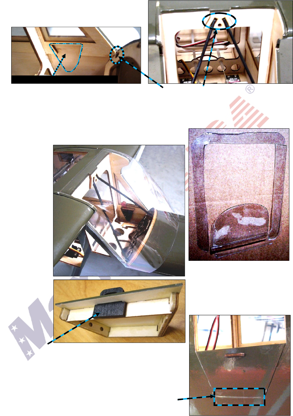
c. If you are not installing the optional throttle and
dashboard, position the carbon-fiber rod cockpit
braces, then secure them with thin CA adhesive.
(Insert the ends of carbon-fiber rod cockpit braces here and here.)
d. You may use one or two optional Maxford USA 1/5-scale pilot figures; however, we recommend you
construct a removable platform above the servos from lightweight scrap wood or plastic, then attach
your pilot figure(s) to this platform. It helps if this platform is easily removable for access to the spring
that connects the wing panels together and for adjustment or replacement of a fuselage-mounted servo.
e. As pictured at the right, use sharp scissors to carefully trim and
test-fit the excess molding-plastic from around the windshield.
f. Once you
have finished
trimming and
fitting the
windshield,
you may use
the supplied
1/4-inch
wood screws
to hold it in
position.
(Some
builders
prefer to
attach their
windshields
with trans-
parent tape or
a suitably-
colored
automotive or
hobby-grade
trim tape.)
g. Position the
black wooden
handle in the
opening on the lower door panel.
i. Secure the handle to the lower door panel with CA adhesive.
j. Position the lower door panel in the bottom half of the opening
on the right side of the fuselage. (NOTE: The built-in magnets
are now holding the lower door panel securely in position.)
k. Form an ‘invisible hinge’ along the entire width of the lower
door panel by applying a strip of transparent tape between the
outside surface of the lower door panel and the fuselage.
(NOTE: Use only totally transparent tape; do not use the more
popular ‘magic mending tape.’)
Typical amount and shape
of the plastic removed
from the windshield.
Page 10 of 14 S121015 Copyright 2012
(
(
N
N
O
O
T
T
E
E
:
:
T
T
h
h
i
i
s
s
s
s
p
p
a
a
c
c
e
e
i
i
s
s
f
f
o
o
r
r
t
t
h
h
e
e
t
t
h
h
r
r
o
o
t
t
t
t
l
l
e
e
c
c
o
o
n
n
t
t
r
r
o
o
l
l
.
.
)
)