
Instruction manual


/
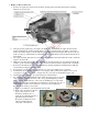
d. Inside each wing panel is a preinstalled string to pull the servo extension wires to the center of the wing;
carefully pull each servo extension through each wing panel for connection to your Y-cable.
e. After installing the servos and connecting the servo extensions,
connect the aileron pushrods between each aileron’s control horn
and servo.
7. Optional Upgrades –
a. If you are using the optional detailed dashboard and throttle
control, position these items inside the cockpit and secure them
at this time with thin CA adhesive.
b. You may also add one or two Maxford USA 1/5-scale pilot
figures inside the top- and bottom-hinged opening side door.
c. If you have access to a suitable body of water, you may replace
the fixed landing gear with a set
of 40-sized Maxford USA floats.
(HINT: You may preview the
detailed float installation
instructions provided with these
floats on our Website at
www.maxfordusa.com.)
(NOTE: All of the optional upgrade items for the L-4 Grasshopper may also be purchased for use with
our ARF model of the Piper J-3 Cub.)
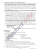
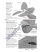
8. Mount the Wing –
a. Identify and stage the V-shaped left & right wing struts and related materials shown below to assemble
and attach the wing to the fuselage.
b. Insert the front joiner (#6)
and rear joiner (#7) into the
root ribs of the wing panels
and slide the left and right
panels firmly together to
form a complete wing.
c. Align and insert the plywood
projections at the middle of
the wing’s leading edge with
the opening behind the
‘windshield’ in the fuselage,
then gently lower the wing
onto the fuselage’s wing
saddle.
d. Place the hold-down plate (#3) over the trailing edge and insert the two hold-down bolts (#4) through the
holes in the plate, through the wing, and into the blind nuts preinstalled in the fuselage.
e. Snug (but do not over-tighten) both hold-down bolts to secure the wing to the fuselage.
f. Place the Grasshopper upside down on a soft surface and test-fit the wing bracing struts (#5) to the wing
and fuselage.
g. Using the predrilled holes in the bottom of the wing and the provided screws, position and attach the
wing bracing struts (#5).
h. Connect the V-shaped end of each wing bracing strut to the bottom side of the fuselage where the
landing gear’s rear hold-down plates are attached (as shown as item #4 in the diagram on page 6).
Page 8 of 10
S110729 Copyright 2011
6. Front joiner