
Instruction manual


/
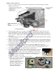
d. Test-fit the vertical
stabilizer into its slot at
the top rear of the
fuselage. (Ensure the
lower portion of the
rudder will align with
but not bind against the
lower end of the
fuselage.)
e. Secure the vertical
stbilizer (#1) into its
slot with thin CA
adhesive.
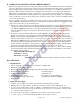
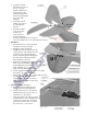
f. Test-fit the rudder’s
control horn and
both elevator
control horns as
shown at the right.
Securely attach all three control horns:
One on the rudder and one on each half of the elevator.
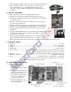
5. Tail Wheel –
a. Test-fit all the pieces of the tail wheel
assembly as shown at the right.
b. Install two wheel collars (#3).
(NOTE: One wheel collar prevents the
vertical portion of the tail wheel’s strut
from being forced upward through
the hole in the tail gear mounting plate;
the other wheel collar keeps the tail
wheel attached to its axle.)
c. Position the mounting plate (#4) and insert the
sharp end of the tail wheel’s strut into
the predrilled hole in the rudder;
using 5-minute epoxy, secure the
sharp end of the strut inside the rudder.
d. Use the supplied CA hinges and thin CA to attach
the rudder to the vertical stabililzer.
e. Using the photo at the right as a guide, make sure that
the tail gear can rotate freely in the
mounting plate (#4) and use screws to
attach the mounting plate to the bottom
of the fuselage.
6. Ailerons and Aileron Servos –
a. Test-fit the ailerons with their wing
panels, control horns and pushrods.
b. Attach an aileron horn to each aileron.
(Predrilled holes show the position of
each aileron’s control horn.)
c. Using the picture at the right as a guide,
mount the aileron servos. (NOTE: Use a
12-inch servo extension in each wing
panel and a 6-inch Y cable to connect
the extensions to your receiver.
Elevator’s
control
horns
Page 7 of 10