
Instruction manual


/
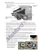
c) Attach your ESC and confirm that the motor runs in the correct direction by connecting the ESC’s
throttle lead to your radio receiver’s throttle channel; switch ON your transmitter and set transmitter’s
throttle and throttle trim controls to minimum; with no propeller on the motor, switch ON your
transmitter and connect the ESC to the battery; after you hear a series of initialization sounds, slowly
raise the transmitter’s throttle to no more than 25% of maximum.
d) Carefully run the motor slowly and only for the few seconds necessary to observe its direction of
rotation. If the motor rotated in the clockwise (correct) direction as viewed from the rear of the
airplane, return the throttle to minimum, disconnect the ESC from the battery, switch OFF the
transmitter, and set your battery and transmitter aside. However, if the motor powered up in the
counterclockwise (wrong) direction, return the throttle control to minimum, disconnect the ESC from
the battery, swap either two of the three ESC-to-motor wires, and repeat the above procedure to
ensure the motor rotates in the correct direction.
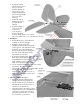
3. Mains Landing Gear Assembly –
(NOTE: If you will use floats, replace this section with the detailed instructions included with the floats.)
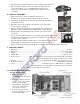
a. Turn the fuselage up-side down. If necessary, spread the main landing gear assembly’s crossmember
wires to align with the precut slots located under the Mylar covering material as shown below.
(IMPORTANT: Do NOT cut away the covering over the slots; instead, leave the Mylar covering
material to be pressed into these slots to help keep the wood inside each slot from getting soaked with
any residual exhaust oil.)
b. Make a clean ‘slice’ in
the Mylar from side-
to-side over the mid-
line of each slot.
c. Position the landing
gear’s front and rear
crossmembers over
their slots to help
locate and poke ‘open’
the Mylar covering the
predrilled mounting
screw holes.
d. Press the landing
gear’s front and rear
crossmember wires
into their slots. Using
the supplied mounting
screws (#5), install the
four hold-down plates
(#4, two across each
cross-member).
e. Locate the wheel collars (#3) as shown and secure each mains wheel (#2) to its axle by tightening the set
screw in each wheel collar.
4. Tail Surfaces –
a. Test-fit the vertical stabilizer, rudder, horizontal stabilizer and two halves of the elevator.
(IMPORTANT: The elevator will REMAIN in two separate halves; one half will be installed on each
side of the vertical stabilizer – otherwise you will not be able to insert the horizontal stabilizer through
its slot at the end of the fuselage.)
b. Slide the horizontal stabilizer through the slot at the end of the fuselage. Center and align the horizontal
stab. at a right angle to the centerline of the fuselage, and secure it in place with thin CA adhesive.
c. Using the supplied CA hinges and thin CA, attach the two halves of elevator to the horizontal stabilizer.
struts
Page 6 of 10
S110729 Copyright 2011