MAXDATA PLATINUM 220 Server System Manual
Contents
Contents 1 Setting up the system 5 Server position ........................................................................................................................................5 Connecting the system ...........................................................................................................................6 Rear Connectors.................................................................................................................................6 Powering up the system .....
BIOS ......................................................................................................................................................25 PCI Auto Configuration.....................................................................................................................26 IDE Auto Configuration.....................................................................................................................26 Boot Options .........................................................
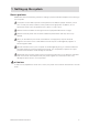
1 Setting up the system Server position Please take note of the following criteria for creating a practical and safe workplace when setting up your computer: The system can be used anywhere the temperature is suitable for people. However, rooms with humidity over 70%, and dusty or dirty areas are not appropriate. In addition, do not expose the server to any temperatures over +30° C or under +10° C. Make sure that the cables connecting the server to peripheral devices are not tight.
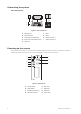
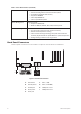
Connecting the system Rear Connectors � � � � � � � � � Figure 1. Rear connectors A. PS/2-Mouse F. NIC 1 B. PS/2-Keyboard G. NIC 2 C. Parallel port (Parallelport) H. USB-Connector 1 D. Serial port A (Serieller Port A) I. USB-Connector 2 E. VGA port Powering up the system At the front of the case, you can find the neccessary controls like power button, reset button and the HDD Leds. Press the power button one time briefly in order to boot the server. � � � � � � � � Figure 2.
2 Server Description This chapter briefly describes the main features of Intel® Server Board S875WP1-E. Table 1 summarizes the major features of the desktop board. Table 1. Server Board Features Feature Description Processors Support for an Intel® Pentium® 4 processor in an mPGA478 package with an 800/533/400 MHz system bus Memory • Four 184-pin DDR SDRAM Dual Inline Memory Module (DIMM) sockets. • Support for up to 4 GB Unbuffered ECC system memory.
Table 1. Server Board Features (continued) BIOS Intel®/AMI BIOS with support for: • Advanced Configuration and Power Interface (ACPI). • 8 megabit symmetrical flash memory. • Support for SMBIOS. • Intel® Rapid BIOS Boot. • Intel® Express BIOS Update. Power Management Support for ACPI: • Suspend to RAM (STR). • Wake on USB, PCI, RS-232, PS/2, LAN, and front panel. Hardware Management Hardware monitor with: • Four fan sensing inputs used to monitor fan activity. • Remote diode temperature sensing.
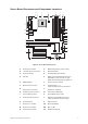
Server Board Connector and Component Locations � � � � � � � �� � �� � �� � � � � � � � � � � � � � � � � � Figure 4. Server Board Components A. System Fan 4 Header O. BIOS Configuration Jumper (J8J2) B. +12V CPU Power Connector P. SCSI LED Header C. Processor Socket Q. Hot Swap Backplane Header D. CPU Fan S. SATA-A1 through SATA-A4 Connector (S875WP1LX only, from left to right: SATA-A4, SATA-A2, SATA-A3, SATA-A1) E. DIMM Sockets T. Chassis Intrusion Header F.
Processor The S875WP1-E server board supports a single Intel® Pentium® 4 processor with an mPGA478 socket. The processor connects to the server board through the mPGA478 socket. The Intel® Pentium® 4 processor can be removed and replaced to accommodate a supported higher speed processor. The server board S875WP1-E supports the following processors. Table 2. Supported Processors Type Designation System Bus L2 Cache Size Pentium® 4 processor with HyperThreading (HT) Technology 2.40, 2.60, 2.80, and 3.
Intel® 875P Chipset The Intel® 875P chipset consists of the following devices: • Intel® 82875P Memory Controller Hub (MCH) with Accelerated Hub Architecture (AHA) bus. • Intel® 82801ER I/O Controller Hub (ICH5-R) with AHA bus. • Intel® 82802AC Firmware Hub (FWH). The MCH is a centralized controller for the system bus, the memory bus, the AGP bus, and the Accelerated Hub Architecture interface. The ICH5-R is a centralized controller for the board’s I/O paths.
Video The server board S875WP1-E contains two separate, mutually exclusive graphics subsystems. You can use either the AGP connector or the ATI Rage XL video controller. When an AGP card is installed, the integrated 8 MB video controller is disabled. AGP Connector AGP is a high-performance interface for graphics-intensive applications. AGP is independent of the PCI bus and is intended for exclusive use with graphical display devices. The AGP bus follows the AGP 3.0 specification.
Table 3.
Parallel Port The 25-pin D-Sub parallel port connector is located on the back panel. In the BIOS Setup program, the parallel port can be set to the following modes: • Output only (PC AT-compatible mode) • Bi-directional (PS/2 compatible) • EPP • ECP Floppy Drive Controller The I/O controller supports one diskette drive that is compatible with the 82077 diskette drive controller and supports both PC-AT and PS/2 modes.
NOTE Computer systems that have an unshielded cable attached to a USB port may not meet FCC Class B requirements, even if no device is attached to the cable. Use s shielded cable that meets the requirements for full-speed devices. Legacy USB support operates as follows: 1. When the user applies power to the computer, legacy support is disabled. 2. POST begins. 3.
Data Storage Serial ATA (SATA) The server board S875WP1-E supports Serial ATA devices using the ICH5-R controller. The ICH-5 provides the following Serial ATA support: • 150 MB/sec transfer rate. • Up to two SATA devices on the server board S875WP1-E. These are indicated by the connectors labeled SATA-B1 and SATA-B2 on the server board. IDE Interfaces The ICH5-R IDE controller has two independent bus-mastering IDE interfaces that can be independently enabled.
Network Interface Controller (NIC) The server board S875WP1-E supports two Network Interface Controllers (NICs), one that runs at 10/100 Mb and is Based on the Intel® 82562ET NIC and the other that runs at one gigabit and is Based on the Intel® 82547EI NIC. When looking at the rear of the chassis, the gigabit NIC is at the left (closest to the video port) and the 10/100 Mb NIC is at the right. You can disable either or both NICs through BIOS Setup.
Table 6. 10/100/1000 Gigabit Ethernet LAN Connector LEDs LED Color LED State Indicates Green (left LED) Off LAN link is not established. On (steady state) LAN link is established. On (brighter and pulsing) The computer is communicating with another computer on the LAN. Off 10 MBit/sec data rate is selected. Green 100 MBit/sec data rate is selected. Yellow 1000 MBit/sec data rate is selected.
The Server Board S875WP1-E supports sleep states S0, S1, S2, S3, S4, and S5. When the server board is operating in ACPI mode, the operating system retains control of the system and the operating system policy determines the entry methods and wake-up sources for each sleep state. Sleep entry and wake-up event capabilities are provided by the hardware but are enabled by the operating system. The following is a summary of the supported sleep states: • S0: Normal running state. • S1: Processor sleep state.
Wake-up Devices and Events Table 8 provides an overview of the devices or events that can wake the computer from specific states. Table 8. Wake-up Devices and Events These devices/events can wake up the computer… …from this state Power button S1, S3, S4 (Note 1), S5 RTC alarm S1, S3, S4 (Note 1), S5 LAN S1, S3, S4 (Note 1), S5 PCI via PME# signal S1, S3, S4 (Note 1), S5 Resume on Ring (back panel Serial Port A) S1, S3 USB S1, S3 PS/2 S1, S3 Notes: 1.
Wake from USB USB bus activity wakes the computer from an ACPI S1 or S3 state. NOTE Wake from USB requires the use of a USB peripheral that supports Wake from USB. Wake from PS/2 Devices PS/2 device activity, such as moving a PS/2 mouse or pressing a key on a PS/2 keyboard, wakes the computer from an ACPI S1 or S3 state.
Fan Connectors Table 9 summarizes the function/operation of the fan connectors. Table 9. Fan Connector Function/Operation Connector Processor fan (CPU FAN) Description • +12V DC connection for a processor fan or active fan heat sink. • Fan is on in the S0 or S1 state. Fan is off when the system is off or in the S3, S4, or S5 state. • Wired to a fan tachometer input of the Hardware Management ASIC. Front and rear chassis fans (FAN1, FAN2, FAN3, and FAN4) • +12V DC connection for a system or chassis fan.
CR7J1 Figure 5. Location of the Standby Power Indicator LED CR7J1 Hardware Management and Monitoring The Hardware Management features enable the board to be compatible with the Wired for Management (WfM) specification. The board has several hardware management features, including the following: • Remote temperature sensing near the Vreg • Power supply monitoring (+5V, +3.3V, 3.3 VSB, +1.5V, and VCCP) to detect levels above or below acceptable values • Fan monitoring though four fan tachometer inputs.
• Setting a user password restricts who can boot the server. The password prompt is displayed before the server is booted. If only the supervisor password is set, the server boots without asking for a password. If both passwords are set, you can enter either password to boot the server. Table 10.
Recovering the CMOS In the unlikely event that the CMOS should be corrupt, it can be cleared by using a jumper setting on the server board. To recover the CMOS and return the settings to the default value: 1. Power down the server and unplug all AC power cables. 2. Remove the cover from the chassis. 3. Move the jumper at jumper block J8G1 to cover pins 2 and three. For the location of jumper block J8G1, see the figure below. ���� � � � Figure 6. Location of Clear CMOS Jumper 4.
PCI Auto Configuration The BIOS can automatically configure PCI devices. PCI devices may be onboard or add-in cards. Auto configuration lets a user insert or remove PCI cards without having to configure the system. When a user turns on the system after adding a PCI card, the BIOS automatically configures interrupts, the I/O space, and other system resources. Any interrupts set to Available in Setup are considered to be available for use by the add-in card.
Booting Without Attached Devices For use in embedded applications, the BIOS has been designed so that after passing the POST, the operating system loader is invoked even if the following devices are not present: • Video adapter • Keyboard • Mouse Fast Booting Systems with Intel® Rapid BIOS Boot These factors affect system boot speed: • Selecting and configuring peripherals properly. • Using an optimized BIOS, such as the Intel® Rapid BIOS.
Server Description
3 Regulatory and Integration Information Product Regulatory Compliance Product Safety Compliance The server board S875WP1-E complies with the following safety requirements: • UL 1950 - CSA 950 (US/Canada) • EN 60 950 (European Union) • IEC60 950 (International) • CE – Low Voltage Directive (73/23/EEC) (European Union) • EMKO-TSE (74-SEC) 207/94 (Nordics) • GOST R 50377-92 (Russia) Product EMC Compliance The server board S875WP1-E has been has been tested and verified to comply with the following
Electromagnetic Compatibility Notices FCC (USA) This device complies with Part 15 of the FCC Rules. Operation is subject to the following two conditions: (1) this device may not cause harmful interference, and (2) this device must accept any interference received, including interference that may cause undesired operation. This equipment has been tested and found to comply with the limits for a Class A digital device, pursuant to Part 15 of the FCC Rules.
Installation Requirements CAUTION Follow these guidelines to meet safety and regulatory requirements when installing this board assembly. Read and adhere to all of these instructions and the instructions supplied with the chassis and associated modules. If the instructions for the chassis are inconsistent with these instructions or the instructions for associated modules, contact the supplier’s technical support to find out how you can ensure that your computer meets safety and regulatory requirements.