
Datasheet
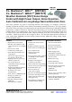


MB7060 & MB7070 Real-time Operation & Timing
175mS after power-up, the XL-MaxSonar
®
is ready to begin ranging. If Pin-4 is left open or held high (20uS or
greater), the sensor will take a range reading. The XL-MaxSonar
®
checks the Pin-4 at the end of every cycle.
Range data can be acquired once every 99mS. Each 99mS period starts by Pin-4 being high or open, after which
the XL-MaxSonar
®
calibrates and calculates for 20.5mS, and after which, thirteen 42KHz waves are sent.
Then for the MB7060, the pulse width (PW) Pin-2 is set high. When an object is detected the PW pin is set low.
If no target is detected the PW pin will be held high for up to 44.4mS (i.e. 58uS * 765cm) (For the most accurate
range data, use the PW output of the MB7060 product.)
For the MB7070 with analog envelop output, Pin-2 will show the real-time signal return information of the
analog waveform.
For both parts, the remainder of the 99mS time (less 4.7mS) is spent adjusting the analog voltage to the correct
level, (and allowing the high acoustic power to dissipate). During the last 4.7mS, the serial data is sent.
MB7060 & MB7070 Real-time Auto Calibration
Each time before the XL-MaxSonar
®
takes a range reading it calibrates itself. The sensor then uses this data to
range objects. If the temperature, humidity, or applied voltage changes during sensor operation, the sensor will
continue to function normally. The sensor does not apply compensation for the speed of sound change verses
temperature to any range readings.
MB7060 & MB7070 Pin Out
GND
Return for the DC power supply. GND (& V+) must be ripple and
noise free for best operation.
V+
Operates on 3.0V to 5.5V. The average (and peak) current draw for 3.3V
operation is 2.1mA (50mA peak) and 5V operation is 3.4mA (100mA peak)
respectively. Peak current is used during sonar pulse transmit.
Pin 5 -
(TX) When Pin 1 is open or held high, the Pin 5 output delivers
asynchronous serial with an RS232 format, except voltages are 0-Vcc.
The output is an ASCII capital “R”, followed by three ASCII character
digits representing the range in centimeters up to a maximum of 765,
followed by a carriage return (ASCII 13). The baud rate is 9600, 8 bits,
no parity, with one stop bit. Although the voltage of 0-Vcc is outside the
RS232 standard, most RS232 devices have sufficient margin to read 0-
Vcc serial data. If standard voltage level RS232 is desired, invert, and
connect an RS232 converter such as a MAX232.
When Pin 1 is held low, the Pin 5 output sends a single pulse, suitable for
low noise chaining (no serial data).
Pin 4 -
(RX) This pin is internally pulled high. The MB7060 & MB7070
will continually measure range and output if the pin is left unconnected
or held high. If held low the MB7060 & MB7070 will stop ranging.
Bring high 20uS or more for range reading.
Pin 3 -
(AN) This pin outputs analog voltage with a scaling factor of
(Vcc/1024) per cm. A supply of 5V yields ~4.9mV/cm., and 3.3V yields
~3.2mV/cm. Hardware limits the maximum reported range on this output
to ~700 cm at 5V and ~600 cm at 3.3V. The output is buffered and
corresponds to the most recent range data.
Pin 2 -
MB7060 (PW) This pin outputs a pulse width representation of
range. To calculate distance, use the scale factor of 58uS per cm.
MB7070 (AE) This pin outputs the analog voltage envelope of the
acoustic wave form.
Pin 1 -
Leave open (or high) for serial output on the Pin 5 output. When
Pin 1 is held low, the Pin 5 output sends a pulse (instead of serial data),
suitable for low noise chaining.
MaxBotix
®
Inc.
MaxBotix, MaxSonar, WR1 & WRA1 are trademarks of MaxBotix Inc.
XL-WR1™ XL-WRA1™ • Patents 7,679,996 • Copyright 2005 - 2012
MB7060
MB7070
Email: info@maxbotix.com
Web: www.maxbotix.com
Page 2
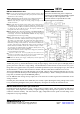
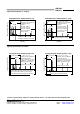
MB7060 & MB7070 Circuit
The sensor functions using active components
consisting of an LM324 and PIC16F690, together
with a variety of other components. The
schematic is shown to provide the user with
detailed connection information.
Part Number: PD10024e