
User Manual

Reliability Demonstration Report
MaxBotix
®
Inc.
Document Release: 05/12/2010, pg. 5 of 10
10
0
MaxBotix, MaxSonar, XL & WR are trademarks of MaxBotix Inc.
v1.1b • 07/2009 • Copyright 2005-2010
Email:
info@maxbotix.com
Web:
www.maxbotix.com
3 Temperature Cycling Life Test
3.1 Test scope
The purpose of this test was to use Thermal Cycling Testing to demonstrate the long-term
operation of our Maxbotix Inc., MaxSonar™ sensor line. (This temperature cycling test
was designed to work in tandem with the mean-life test to establish the ability of the
MaxSonar™ sensor to operate in temperature conditions ranging between -40°C and
+65°C.) The test was conducted at Maxbotix Inc. starting on February 24, 2010 and
concluding on April 05, 2010.
3.2 Test Samples
Temperature Cycling was carried out on a total of 20 units. Of these 10 were issued from
production to represent the XL product line and 10 were issued to represent the WR
product line. All units were prescreened using the method as regular production parts.
3.3 Test Conditions
To achieve this goal a test was designed to expose the parts to the specified –40°C to
+65°C temperature range for 177 temperature cycles with 30 minutes dwell at each cycle
extreme. The temperature chamber used was a Tenney JR.
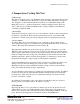
The temperature chamber was monitored for proper operation. In addition, one of the
WR unit’s analog voltage envelope was also connected to the data logger and the analog
offset voltage for this unit was recorded. Because the analog envelope offset voltage is a
function of temperature, this voltage can verify that the product under test matches the
chamber temperature. Please reference the Appendix for a detailed plot of time verses
temperature showing this output in relation to the chamber temperature.
For the first 100 temperature cycles the product operation was verified twice daily (once
during a cold cycle and once during a hot cycle) in order to verify the following:
Minimum waveform voltage, maximum waveform voltage, verified correct transmit
burst, and verified the analog envelope output signal.
At cycle 101 full product testing was completed at each temperature extreme. In addition
product was removed from the temperature chamber and the product received the full
production test. This removable process required unsoldering of lead wires from the
products. No failures occurred.
An additional 75 temperature cycles were carried out with the product non-powered.
Product operation was again verified. No failures occurred.
3.2 Test Results
By testing 20 units for 177 cycles with a test duration 317 hours, the product recieved
3540 cumulative cycles over 6340 cumulative hours. During the course of this test no
failures were observed, with a calculated mean time between failure (MTBF) of 229,139
hours. Reference the Appendix for calculations related to the MTBF value.