
Datasheet


MaxBotix
®
Inc.
Copyright 2005 - 2021 MaxBotix Incorporated
Patent 7,679,996
ParkSonar
®
-EZ Series
Page 6
Web: www.maxbotix.com
PD13426g
MaxBotix Inc., products are engineered and assembled in the USA.
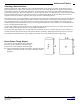
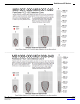
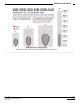
Selecting a Detection Zone
Different applications require different sensors. The ParkSonar-EZ sensor product line offers varied detection zones
(detection distances) to allow you to select the best sensor to meet your needs. Each sensor is calibrated to provide the
approximate detection zone shown in this datasheet. This allows end users to select the part number that matches their
given sensing application. Each part number has a consistent field of detection so additional units of the same part number
will have similar detection zones. The beam patterns are provided to help identify an estimated detection zone for an
application based on the acoustic properties of a target versus the plotted beam patterns.
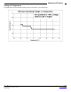
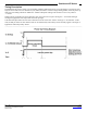
Each detection zone is a 2D representation of the detection area of the sensor. The detection zone is actually shaped like a
3D cone (having the same detection pattern both vertically and horizontally). Detection patterns for dowels are used to
show the detection zone of each sensor. Dowels are long cylindered targets of a given diameter. The dowels provide
consistent target detection characteristics for a given size target which allows for easy comparison of one ParkSonar-EZ
sensor to another ParkSonar-EZ sensor.
For each part number, the four patterns (A, B, C and D) represent the detection zone for a given target size. Each beam
pattern shown is determined by the sensor’s part number and target size.
The actual beam angle changes over the full range. Use the detection zone for a specific target at any given distance to
calculate the beam angle for that target at the specific distance. Generally, smaller targets are detected over a narrower
beam angle and a shorter distance. Larger targets are detected over a wider beam angle and a longer range.
Beam Pattern Target Shapes
A 6.1-mm (0.25-inch) diameter dowel 4ft length
B 2.54-cm (1-inch) diameter dowel 4ft length
C 8.89-cm (3.5-inch) diameter dowel 4ft length
D 11-inch wide board 4ft in length moved left to right with the board
parallel to the front sensor face. This shows the sensor’s range
capability.