
Data Sheet

Page 9
Web: www.maxbotix.com
PD11500k
MaxBotix
®
Inc.
Copyright 2005 - 2012 MaxBotix Incorporated
Patent 7,679,996
HRXL-MaxSonar
®
- WR/WRC
™
Series
MaxBotix Inc., products are engineered and assembled in the USA.
Sensor Timing Diagrams Cont.
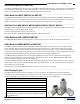
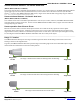
Triggered—Real-time Operation Timing
Real-time or triggered operation allows users to take advantage of a few functions unavailable during free run mode.
When operating in triggered mode, an unfiltered maximum refresh rate can be achieved. This triggered operation allows
users to range targets moving away from or closer to the sensor faster than 240mm per reading.
Users can enter and remain in the real-time or triggered operation by making sure that before the end each range cycle, the
voltage level on Pin 4 is set low. After the sensor has completed the last reading, then Pin 4 is brought high. When Pin 4 is
brought high, a brand new range cycle starts and the HRXL-MaxSonar-WR will output the most recent range data without
filtering.
Readings during triggered operation are less accurate than the filtered operation by approximately ±5-mm. Because the
range readings are not filtered, noise tolerance can be greatly reduced. Care should be taken to make sure that only one
sensor is sampling range at a time.
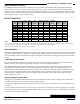
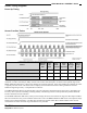
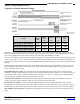
Pulse Width data sent (Colum A) - Column A shows the approximate time that the sensor starts to output the pulse
width data. The Pulse Width output time can be as short as 300uS (minimum reported distance). For 5 meter sensors, the
pulse width can take as long as 5000uS (maximum reported distance) to be sent. For 10 meter sensors the Pulse Width
can take as long as 9999uS (maximum reported distance) to be sent.
Serial data sent (Colum B) - Column B shows the approximate time during each range cycle when the serial data is
output for the sensor. Range data takes ~8mS to be reported from the serial data output.
RX Pin set low (Column C) - When operating the HRXL-MaxSonar-WR in Triggered Operation, Pin 4 is must be
brought high for a time frame greater than 20uS (0.02mS) and less than the time in Column C in the chart above. If Pin 4
remains high for a period of time greater than the value in Column C, the sensor will switch into free-run filter operation.
End of Range Cycle (Colum D) - Column D shows the approximate time each range cycle takes to complete for each
sensor.
Product
Maximum
Refresh
Rate
Pulse
Width
sent
(A)
Serial
Data sent
(B)
RX Pin
set low
(C)
End of
range
cycle
(D)
MB7360, MB7367, MB7380, MB7387 7.5 Hz ~118mS ~123mS ~132mS ~133mS
MB7364, MB7369, MB7384, MB7389 6.67Hz ~135mS ~140mS ~147mS ~148mS
MB7363, MB7366, MB7383, MB7386 6Hz ~148mS ~158mS ~165mS ~166mS
Power up timing has
already occurred