
Data Sheet

Page 6
Web: www.maxbotix.com
PD11500k
MaxBotix
®
Inc.
Copyright 2005 - 2012 MaxBotix Incorporated
Patent 7,679,996
HRXL-MaxSonar
®
- WR/WRC
™
Series
MaxBotix Inc., products are engineered and assembled in the USA.
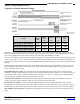
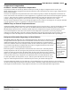
Mechanical Dimensions Continued
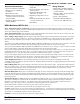
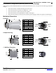
1” BSPP Pipe Threading
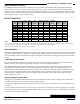
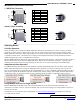
30mm1.5 Pipe Threading
_______________________________________________________________________________________________________________________________________
Operating Modes
Free-Run Operation
When operating in free run mode, the HRXL-MaxSonar-WR sensors are designed to be used in a variety of outdoor,
industrial, or indoor situations. Many acoustic noise sources will have little to no effect on the reported range of the
HRXL-MaxSonar-WR sensors. Most range readings are accurately reported. If the range readings are affected, the effect
is typically less than 5-mm
1
. This allows users to employ real-time ultrasonic distance sensing without the need for
additional supporting circuitry or complicated user software.
Multiple HRXL-MaxSonar-WR sensors can be operated in the same general locations. The internal noise filter is able to
filter out the ultrasonic noise from other HRXL-MaxSonar-WR sensors with minimal interference. Typically, when
operating with multiple sensors, the range readings will be within ±1 cm of the actual range to the intended target.
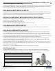
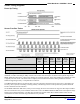
Independent Sensor Operation
The HRXL-MaxSonar-WR sensors have the capability to operate independently when the user desires. When using the
HRXL-MaxSonar-WR sensors in single or independent sensor operation, it is easiest to allow the sensor to free-run.
Free-run is the default mode of operation for all of the MaxBotix Inc., sensors. The HRXL-MaxSonar-WR sensors have
three separate outputs that update the range data simultaneously: Analog Voltage, Pulse Width, and Serial Data. Below
are diagrams on how to connect the sensor for each of the three outputs for single or independent sensor operation.
Using Multiple Sensors in a Single System
Multiple HRXL-MaxSonar-WR sensors can be used simultaneously in the same environment with little to no
interference (cross-talk). Even so, some cross-talk may still occur for users wishing to use a large number of sensors in
the same environment.
If interference is occurring in the sensor setup please visit www.maxbotix.com/chaining for diagrams on correcting
cross-talk between sensors.
Notes:
1
Refer to section that compares WR to WRC on page 4
A
1.52” 38.5 mm
B
1.29” dia. 33.0 mm dia.
C
0.22” 5.5 mm
D
1.30” 33.1 mm
E
0.10” 2.54 mm
F
1” — BSPP
G
0.78” 19.81 mm
Weight, 1.21 oz., 34.3 grams
Values Are Nominal
B
E
F
D
A
C
V+
Pin 1
Pin 2
Pin 3
Pin 4
Pin 5
GND
G
G
A
1.52” 38.5 mm
B
1.17” dia. 29.7 mm dia.
C
0.22” 5.5 mm
D
1.30” 33.1 mm
E
0.10” 2.54 mm
F
30mm 1.5
G
0.78” 19.81 mm
Weight, 1.10 oz., 31.1 grams
Values Are Nominal
B
E
F
D
A
C
V+
Pin 1
Pin 2
Pin 3
Pin 4
Pin 5
GND