
Data Sheet

Page 2
Web: www.maxbotix.com
PD11500k
MaxBotix
®
Inc.
Copyright 2005 - 2012 MaxBotix Incorporated
Patent 7,679,996
HRXL-MaxSonar
®
- WR/WRC
™
Series
MaxBotix Inc., products are engineered and assembled in the USA.
______________________________________________________________________________________________________________________________________
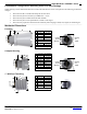
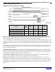
HRXL-MaxSonar-WR Pin Out
Pin 1- Temperature Sensor Connection: Leave this pin unconnected if an external temperature sensor is not used. For best
accuracy, this pin is optionally connected to the HR-MaxTemp temperature sensor. Some additional information for the temperature
sensor can be found on page 7 of the datasheet.
Pin 2- Pulse Width Output: This pin outputs a pulse width representation of the distance with a scale factor of 1uS per mm. The
pulse width output is sent with a value within 0.5% of the serial output.
Pin 3- Analog Voltage Output: This pin outputs a single ended analog voltage scaled representation of the distance. This output
is referenced to the sensor ground and Vcc. After the ~50mS power up initialization, the voltage on this pin is set to a low voltage.
Once the sensor has completed a range reading the voltage on this pin is set to the voltage corresponding to the latest measured
distance.
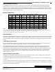
The 5-meter sensors (MB7360, MB7364, MB7369, MB7380, MB7384, and MB7389) use a scale factor of (Vcc/5120) per 1-mm. The
distance is output with a 5-mm resolution. The analog voltage output is typically within ±5-mm of the serial output.
The 10-meter sensors (MB7363, MB7366, MB7383, and MB7386) use a scale factor of (Vcc/10240) per 1-mm. The distance is output
with a 10-mm resolution. The analog voltage output is typically within ±10-mm of the serial output.
Using a 10-bit analog to digital converter with the 5-meter sensors, one can read the analog voltage counts (i.e. 0 to 1023) directly and
just multiply the number of counts in the value by 5 to yield the range in mm. For example, a converted value of 60 corresponds to
300-mm (where 60 x 5 = 300), and 1000 counts corresponds to 5,000-mm (where 1000 x 5 = 5,000-mm).
Using a 10-bit analog to digital converter with the 10-meter sensors, one can read the analog voltage counts (i.e. 0 to 1023) directly
and just multiply the number of counts in the value by 10 to yield the range in mm. For example, 30 counts corresponds to 300-mm
(where 30 x 10 = 300), and 1000 counts corresponds to 10,000-mm (where 1000 x 10 = 10,000-mm).
Pin 4- Ranging Start/Stop: This pin is internally pulled high. If this pin is left unconnected or held high, the sensor will
continually measure and output the range data. If held low, the HRXL-MaxSonar-WR will stop ranging. Bring high for 20uS or longer
to command a range reading.
Filtered Range Data: When pin 4 is left high on the sensors, the sensors will continue to range. The data that is output includes a
filter for increased accuracy. The sensors will output the range based on recent range information. The filter does not affect the speed
at which data is made available to the user but instead allows for more consistent range information to be presented. For sensor
specific timing and filter information refer to pages 8 and 9.
Real-time Range Data: When pin 4 is low and then brought high, the sensor will operate in real time and the first reading output
will be the range measured from this first commanded range reading. When the sensor tracks that the RX pin is low after each range
reading, and then the RX pin is brought high, unfiltered real time range information can be obtained. For timing information please
refer to pages 8 and 9.
Pin 5-Serial Output: The MB736X sensors have an RS232 data format (with 0V to Vcc levels) and the MB738X sensors have a
TTL outputs. The output is an ASCII capital “R”, followed by four ASCII character digits representing the range in millimeters,
followed by a carriage return (ASCII 13). The maximum range reported is 4999 mm (5-meter models) or 9998 mm (10-meter
models). A range value of 5000 or 9999 corresponds to no target being detected in the field of view.
The serial data format is 9600 baud, 8 data bits, no parity, with one stop bit (9600-8-N-1).
Because the data is presented in a binary data format, the serial output is most accurate .
V+ Pin 6 - Positive Power, Vcc: The sensor operates on voltages from 2.7V - 5.5V DC. For best operation, the sensor requires that
the DC power be free from electrical noise. (For installations with known dirty electrical power, a 100uF capacitor placed at the sensor
pins between V+ and GND will typically correct the electrical noise.)
GND Pin 7 – Sensor ground pin: DC return, and circuit common ground.
Range Outputs
• Pulse width, 1uS/mm resolution
• Analog Voltage, 5-mm resolution
(5-meter sensors)
• Analog Voltage, 10-mm resolution
(10-meter sensors)
• Serial, 1-mm resolution
• Available in RS232 (MB7360
series) or TTL (MB7380 series)
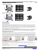
General Characteristics
• Low cost ultrasonic rangefinder
• Detection out to 5-meters or
10-meters
• Resolution of 1-mm
• Distance sensor from 30-cm to
5-meters or 50-cm to 10-meters
based on model
• Excellent
2
Mean Time Between
Failure (MTBF)
• Triggered operation yields real-time
range data
• Free run operation with superior
noise rejection
3
• Operating temperature range
from -40°C to +65°C
• Operating voltage from 2.7V to
5.5V
• Nominal current draw of 2.3mA at
3.3V, and 3.1mA at 5V
• IP67 Rated