
Data Sheet

Page 10
Web: www.maxbotix.com
PD11500k
MaxBotix
®
Inc.
Copyright 2005 - 2012 MaxBotix Incorporated
Patent 7,679,996
HRXL-MaxSonar
®
- WR/WRC
™
Series
MaxBotix Inc., products are engineered and assembled in the USA.
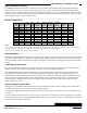
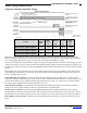
Temperature Compensation
On Board – Internal Temperature Compensation
The speed of sound in air increases by about 0.6 meters per second, per degree centigrade. Because of this, each
HRXL-MaxSonar-WR is equipped with an internal temperature sensor which allows the sensor to apply compensation for
speed of sound changes.
The actual air temperature of the path between the sensor and the target may not match the temperature measured at the
sensor itself. Sensors can be mounted in vertical applications, or applications where the environment temperature gradient
is severe. These users may experience a temperature measurement error which will affect the sensor accuracy. For
example, buildings with a height of 3-meters can have floor to ceiling temperature variations of 5°C or more.
Because of these temperature effects, users desiring the highest accuracy output are encouraged to use a properly mounted
external temperature sensor or to manually account for this measurement error.
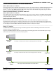
HR-MaxTemp, an External Temperature Sensor
Although the HRXL-MaxSonar-WR has an internal temperature sensor; for best accuracy, users are encouraged to use the
optional external temperature sensor. On power-up, the HRXL-MaxSonar-WR will automatically detect an attached
HR-MaxTemp temperature sensor and begin to apply temperature compensation using the external temperature sensor.
The external temperature sensor allows for the most accurate temperature compensation, by allowing temperature
readings to be taken that better reflect the composite temperature of the acoustic ranging path. For best results, users are
encouraged to connect the temperature sensor midway between the HRXL-MaxSonar-WR and the expected target.
_______________________________________________________________________________________________________________________________________
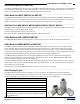
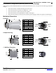
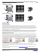
Background Information Regarding our Beam Patterns
Each HRXL-MaxSonar-WR sensor has a calibrated beam pattern. Each sensor is matched to provide
the approximate detection pattern shown in this datasheet. This allows end users to select the part
number that matches their given sensing application. Each part number has a consistent field of
detection so additional units of the same part number will have similar beam patterns. The beam plots
are provided to help identify an estimated detection zone for an application based on the acoustic
properties of a target versus the plotted beam patterns.
Each beam pattern is a 2D representation of the detection area of the sensor. The beam pattern is
actually shaped like a 3D cone (having the same pattern both vertically and horizontally). Beam
patterns for dowels are used to show the beam pattern of each sensor. Dowels are long cylindrical
targets of a given diameter. The dowels provide consistent target detection characteristics for a given
size target which allows easy comparison of one MaxSonar sensor to another MaxSonar sensor.
For each part number, the four patterns (A, B, C, and D) represent the detection zone for a given
target size. Each beam pattern shown is determined by the sensor’s part number and target size.
The actual beam angle changes over the full range. Use the beam pattern for a specific target at any given distance to
calculate the beam angle for that target at the specific distance. Generally, smaller targets are detected over a narrower
beam angle and a shorter distance. Larger targets are detected over a wider beam angle and a longer distance.
People Sensing:
For users that
desire to detect
people, the
detection area to
the 1-inch
diameter dowel, in
general, represents
the area that the
sensor will
reliably detect
people.