
User's Manual

47
RIOTRONIC X+
User Manual
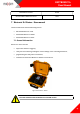
7.2. Device outlook
7.2.1. Keypad
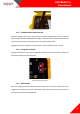
Blaster is equipped with membrane keypad at the front panel. Each key has selective
backlight and only active keys are lighted.
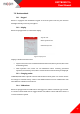
7.2.2. Display
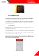
Blaster is equipped with 3,5” LCD colour display.
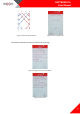
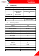
Figure 44. Display areas
Display is divided into three areas:
Top bar area, where user can find information about time, battery status, NFC status
and blasting name,
Main operation area, where are all information about currently performed
operation, Function keys area, where current function of F1 and F2 keys is displayed.
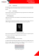
7.2.3. Charging socket
CHARGE/LINK socket is placed at the left side of Blaster’s front panel. It is used to connect
the charger or external battery. There is also RS485 interface used to communicate with
other Blasters or Remote control device.
7.2.4. USB sockets
Blaster is equipped with two USB sockets. The bigger one, USB1 is a USB host type A socket.
It is used to connect flash drive or Logger. Smaller one, USB2 is a micro USB device socket. It
is used to firmware upload.
Top bar area
Main operation area
Function keys area