TECHNICAL MANUAL 2013 SPLIT MONO DC INVERTER MODELS BDS28A BDS35A This manual has been created for informative purpose. The company declines every responsibility for the results of projecting or installation based on the explanations and the technical specifications given in this manual. Is besides forbidden the reproduction under any form of the texts and of the figures contained in this manual.
Serie / Series / Serie / Serie TECHNICAL MANUAL MONO DC INVERTER Emissione / Issue Ausgabe / Emission 04 - 2013 Sostituise / Supersade Ersetzt / Remplace - Catalogo / Catalogue / Katalog / Catalogue MTE01028D2505-00 2
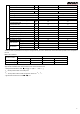
Index 1. SPECIFICATIONS ......................................................................................................................................4 2. CHARACTERISTICS DATA........................................................................................................................6 2.1 Operation characteristic curve ..................................................................................................................6 2.2 Capacity variation ratio according to temperature ..
1. SPECIFICATIONS Models of indoor units BDS28A BDS35A Rated voltage 220-240V ~50Hz Total capacity Cooling Power input Rated current S.E.E.R. Total capacity Heating kW 2,5(0,7 ~ 4,4) 3,5(0,7 ~ 4,5) Btu/h 8,53(2,3 ~ 15,00) 11,9(2,3 ~ 15,3) W 520 900 A 2,3 4,0 W/W 7,5-A++ 7-A++ kW 2,7(0,7 ~ 4,8) 3,5(0,7 ~ 5,5) Btu/h 9,3(2,4 ~ 16,3) 12,4(2,4 ~ 18,7) Power input W 565 895 Rated current A 2,37 7,5 S.C.O.P.
Fan motor capacitor Air flow volume of outdoor unit μF / / m³/h 2000 2000 Fan type-piece Axial-flow Fan diameter mm Φ445 Defrosting method Climate type T1 T1 I I IP24 IP24 Mpa 3,8 3,8 Mpa 1,2 1,5 Isolation Connecting pipe Φ445 Automatic Defrosting Moisture protection Permissible excessive operating pressure for the discharge side Permissible excessive operating pressure for the suction side Sound pressure level dB(A) 49/-/- 50/-/- Sound power level dB(A) 59/-/- 60/-/- Dim
2. CHARACTERISTICS DATA 2.1 Operation characteristic curve Heating Cooling 10 Condition Indoor:DB27 WB19 8 Outdoor:DB35 WB24 Indoor air flow: Super High Pipe length: 5m 6 Condition Indoor:DB20 Outdoor:DB7 Indoor air flow:Super High Pipe length: 5m 8 BDS35A Current (A) Current (A) 10 BDS28A 4 BDS35A 6 BDS28A 4 2 2 0 0 15 20 30 40 60 70 80 0 90 0 15 20 30 40 50 60 70 80 90 Compressor speed (rps) Compressor speed (rps) 2.
Heating: Temperature conditions (°C) Indoor Outdoor 20/15 7/6 Model name BDS28A BDS35A Standard pressure P(MPa) 2,0~2,6 Heat exchanger pipe temp. T1 (°C) T2 (°C) In: 33~35 Out: 42~44 Indoor fan speed Outdoor fan speed Super high Super high In: 3~5 Out: 3~5 Compressor revolution (rps) 41 55 Notes: (1) Connecting piping condition: 5m. (2) T1: Outlet and inlet pipe temperature of evaporator. T2: Outlet and inlet pipe temperature of condenser.
4.
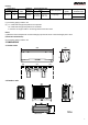
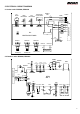
5. ELECTRICAL CIRCUIT DIAGRAM 5.1 Indoor units: BDS28A, BDS35A RECEIVER AND TUBE DISPLAY BOARD TEMP.SENSOR AP1 ROOM TEMP.SENSOR M1 0 L BU(WH) N YEG N M4 M3 M2 SWING MOTOR(U.D1) YEG N EVAPORATOR SWING-UD2 HEALTH-L BK 3 BN YEGN TERMINAL BOARD PE SWING-UD1 BU 2 BN K7 PRINTED CIRCUIT BOARD CONN WIRE N(1) BK L-OUT AC-L XT1 BU N COM-OUT DISP1 DISP2 AP2 SWING MOTOR(L.
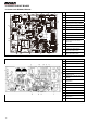
6. PRINTED CIRCUIT BOARD 6.
7. Control functions 7.1. Temperature Parameters • Indoor preset temperature (Tpreset) • Indoor ambient temperature (Tamb) 7.2. Basic functions Once energized, the compressor should in no way be restarted unless after at least 3-minute time interval. In case of having memory function, for the first energization, the compressor will be started without 3-minute lag, if being under the condition of power-off, and the compressor will have 3-minutes delay to be started under the condition of power-on.
7.2.2 Dehumidifying mode 7.2.2.1 The condition and process of dehumidifying If Tamb. > Tpreset, DRY mode will act, the indoor fan, outdoor fan and compressor will run, and indoor fan will run at low speed. If Tset - 2°C ≤ Tambient ≤ Tpreset, the unit will keep running in the original mode. If Tam. ≤ Tset - 2°C, the compressor will stop running, the outdoor fan will delay 30 seconds to stop and the indoor fan will run at low speed. 7.2.2.2 Protection function Protection is the same as that under COOL mode.
7.2.3.3 Protection function ♦ Anti-cold – wind protection In HEAT mode, in order to prevent the indoor unit from blowing out cold wind, each time the compressor starts, the indoor fan will delay 3 minutes after the compressor to run at the latest and it can adjust fan speed automatically when temperature is low. ♦ Overcurrent protection Overcurrent protection is the same with that in COOL mode.
② Protection a) In cooling operation, protection is the same as that under the cooling mode; b) In heating operation, protection is the same as that under the heating mode; c) When ambient temperature changes, operation mode will be converted preferentially. Once started, the compressor will remain unchanged for at least 6 minutes. 7.2.
⑦ Faults of temperature sensors Designation of sensors Indoor ambient temperature Indoor tube temperature Outdoor ambient temperature Outdoor tube temperature Exhaust Overload Faults The sensor is detected to be open-circuited or short-circuited for successive 30 seconds. The sensor is detected to be open-circuited or short-circuited for successive 30 seconds. The sensor is detected to be open-circuited or short-circuited for successive 30 seconds.
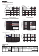
8.3 Flashing LED of Indoor/Outdoor unit and primary judgement No 1 2 Malfunction High pressure protection of system Antifreezing protection 3 Refrigerant leakage protection 4 High discharge Temperature protection of compressor Display Method of Indoor Unit Display Method of Outdoor Unit Indicator has 3 kinds of display Indicator Display (during status and they will be displayed blinking, ON 0.5s and OFF circularly every 5s. 0.
10 11 Malfunction protection of jumper cap Gathering refrigerant 12 Indoor ambient temperature sensor is open/short circuited 13 Indoor evaporator temperature sensor is open/short circuited C5 F0 F1 F2 Blinks 15 times Wireless remote receiver and button are effective, but can not dispose the related command Blinks 1 time When the outdoor unit receive signal of Gathering refrigerant, the system will be forced to run under cooling mode for gathering refrigerant Blinks 1 time Blinks 17 time B
19 Decrease frequency due to high air discharge F9 Blinks 9 times 20 Limit/decrease frequency due to antifreezing FH Blinks 2 times 21 DC generatrix voltage is too high PH Blinks 11 times 22 Voltage of DC bus-bar is too low PL 23 24 25 26 Compressor Min frequence in test state Compressor rated frequence in test state Compressor Max frequence in test state Compressor intermediate frequence in test state Blinks twice Blinks 13 times Blinks 21 times P0 Blinks 0.25Hz Blinks 0.
30 31 32 33 34 Module high temperature protection Decrease frequency due to high temp.
42 Indoor unit and outdoor unit does not match LP 43 Failure start-up LC Blinks 11 times 44 Malfunction of phase current detection circuit for compressor U1 Blinks 13 times 45 Malfunction of voltage dropping for DC bus-bar U3 Blinks 20 times Malfunction of 46 complete unit’s current detection U5 Blinks 19 times compressor and outdoor fan motor can’t work - During cooling and drying operation, compressor will stop while indoor fan will operate.
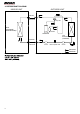
8.4. How to check simply the main part 8.4.1 Indoor Unit: 8.4.1.1 Temperature sensor malfunction (F1/F2) F1 and F2 malfunction Is the wiring terminal between temp.
8.4.1.2 Indoor fan does not operate (H6 Malfunction) Possible causes: 1. Fan motor is locked; 2. The feedback terminal of PG motor is not connected tightly; 3. The control terminal of PG motor is not connected tightly; 4. Motor is damaged; 5. Malfunction of the rotation speed detection circuit of the mainboard. See the flow chart below: “H6” is displayed on the unit. Stir the fan blade with a hand when the unit is DE-ENERGIZED.
8.4.1.3. Jumper cap malfunction (C5) Possible causes: 1. There is no jumper cap on the controller; 2. Jumper cap is not inserted properly and tightly; 3. Jumper cap is damaged; 4. Controller is damaged. See the flow chart below: C5 is displayed on the unit. Is there jumper cap on the mainbaord? Yes No Install a matching jumper cap. Is the malfunction eliminated? No Is the jumper cap inserted incorrectly or improperly? No No Yes Re-insert the jumper cap.
8.4.1.4 Communication Malfunction (E6) 1. Check if connection wire between indoor and outdoor units and wire inside the unit are connected well. 2. Check if mainboard of indoor or outdoor unit is damaged. Communication malfunction of indoor unit Power off the unit and check if the connecting wire of indoor and outdoor unit and wiring of electric box are correct. Is wire connected correctly? No Connect wires according to the wiring diagram Is malfunction removed? No Yes Power off the unit.
8.4.2 Outdoor Unit: 8.4.2.
8.4.2.2. Capacitor charging malfunction (Fault with outdoor unit) (AP1 below refers to the outdoor control panel) Main detection point: • Use AC voltmeter to check if the voltage between terminal L and N on the wiring board is within 210VAC ~ 240VAC. • If the reactor (L) is correctly connected? If the connection is loose or fallen? If the reactor (L) is damaged? Fault diagnosis proess: Switch on the unit and wait 1 minute. Use DC voltmeter to measure the voltage on the two ends of electrolytic capacitor.
• If the working loads of the machine are too hight? If the radiation is good? • If the charge volume of refrigerant is correct? Fault diagnosis process: Energize and switch on IPM Protection occurs after the machine has run for a periode of time? Yes Yes Please confirm: 1. In the indoor and outdoor heat exchangers are obstructed by other objects which affect the heat exchange of indoor and outdoor unit. 2. If the indoor and outdoor fans are working normally? 3.
8.4.2.4. High temperature and overload protection diagnosis (AP1 herinafter refers to control board of the outdoor unit) Main detection point: ● Is outdoor ambient temperature in normal range? ● Are the outdoor and indoor fans operating normally? ● Is the heat dissipation environment inside and ouside the unit is good? Overheat and high temperature protection Yes Normal protection, please operate it after the outdoor ambient temp. is normalized.
8.4.2.
8.4.2.8 Power factor correction (PFC) fault (a fault of outdoor unit) (AP1 hereinafter refers to the control board of the outdoor unit) Main detection point: ● Check if the reactor (L) of the outdoor unit and the PFC capacitor are broken? The failure diagnosis is as follows: Start Check wiring of the reactor (L) of the outdoor unit and the PFC capacitor Yes Whether there is any damage or short-circuit? Replace it as per the wiring diagram and reconnect the wires.
8.4.2.9 Communication malfunction (following AP1 for outdoor unit control board) Main detection point: ● Detect the indoor and outdoor units connection wire and indoor and outdoor units inside wiring is connect well or not, if is there any damage? ● Is there any damage for the indoor unit mainboard communication circuit? Is communication circuit damaged? The flow chart for the malfunction detect: Start No Did the unit operate normally before the failure occurs.
Appendix 1: Resistance table for indoor/outdoor ambient temperature sensors (numerical value of resistance) (15K) Temp. (°C) Resistance (kΩ) 32 Temp. (°C) Resistance (kΩ) Temp. (°C) Resistance (kΩ) Temp. (°C) Resistance (kΩ) -19 138.100 20 18.750 59 3.848 98 1.071 -18 128.600 21 17.930 60 3.711 99 1.039 -17 121.600 22 17.140 61 3.579 100 1.009 -16 115.000 23 16.390 62 3.454 101 0.980 -15 108.700 24 15.680 63 3.333 102 0.952 -14 102.900 25 15.000 64 3.
Appendix 2: Resistance table for indoor/outdoor tube temperature sensor (20K) Temp. (°C) Resistance (kΩ) Temp. (°C) Resistance (kΩ) Temp. (°C) Resistance (kΩ) Temp. (°C) Resistance (kΩ) -19 181.400 20 25.010 59 5.130 98 1.427 -18 171.400 21 23.900 60 4.948 99 1.386 -17 162.100 22 22.850 61 4.773 100 1.346 -16 153.300 23 21.850 62 4.605 101 1.307 -15 145.000 24 20.900 63 4.443 102 1.269 -14 137.200 25 20.000 64 4.289 103 1.233 -13 129.900 26 19.
Appendix 3: form for indoor/outdoor unit’s air exhaust temperature sensor numerical value of resistance Temp. (°C) 34 Resistance (kΩ) Temp. (°C) Resistance (kΩ) Temp. (°C) Resistance (kΩ) Temp. (°C) Resistance (kΩ) -29 853.500 10 98.000 49 18.340 88 4.754 -28 799.800 11 93.420 50 17.650 89 4.609 -27 750.000 12 89.070 51 16.990 90 4.469 -26 703.800 13 84.950 52 16.360 91 4.334 -25 660.800 14 81.050 53 15.750 92 4.204 -24 620.800 15 77.350 54 15.170 93 4.
Via Gettuglio Mansoldo (Loc. La Macia) 37040 Arcole Verona, Italy Tel. +39 - 045.76.36.585 r.a. Fax +39 - 045.76.36.551 r.a. www.maxa.it e-mail: maxa@maxa.