
Instruction Manual

English Manual: Compact Retract 12/24V, Version 2 14/04/2005
To ensure a proper installation, correct usage and long-lasting enjoyment of this
equipment, please take time to read this manual thoroughly.
TABLE OF CONTENTS
1 Positioning of Unit 4
2 Location of Auxiliary Equipment 4
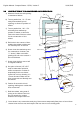
3 Mechanical installation General 5
3.2 Determining & Marking up Position 6
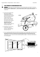
3.3 Construction of the Hull Opening & Closing Plate 7
3.4 Final Fitting of the Mounting Base to the Hull 8
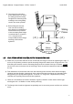
3.5 Final Fitting of the thruster Unit to the Mounting Base 8
3.6 Fitting of Hull Closing Plate 10
3.7 Final Adjustment and Set-Up of Thruster Unit 11
4 Electircal Installation (General) 11
4.2 Control Panel Installation 11
4.3 Control System 12
4.4 Control Panel & Thruster Control Box fucntions & Modes of Operation 13
a) General Remarks 13
b) Manual Mode 13
c) Automatic set-up Mode 14
d) Normal Operation Mode 14
4.5 Battery Requirements 16
4.6 Power Cable Sections (battery to Relay) 16
4.7 Power Fuse 17
5 Operation Limitations 17
6 Basic Maintenance 18
DIAGRAMS
1) Build Diagram 19
2) Wiring of Control Box 20
3) Control Wiring 21
4) Power Cable Connections 22
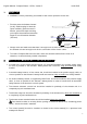
Your thruster is a highly technical product and should be treated as such. The employment of a
qualified marine personnel, with bow and stern thruster installation experience is strongly adviced.
Where possible, the boat manufacturers architect, design departments and/or shipyard should be
consulted, prior to installation taking place. For any boat requiring official classification, bodies of
approval should also be consulted at the earliest opportunity.
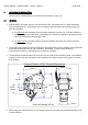
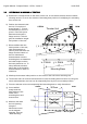
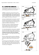
Your thruster should be delivered with the following parts:
2
Thruster assembly with integrated
thrusters motor, up / down motor,
motor coupling, leg and propellers
Plaque for closing
plate (kit)
Directional Relay Box Control Box
Control Panel (Grey) 25m Control Cable Manual