
Owner's manual


Max Machinery, Inc. G Series User Manual © Copyright 2013 Rev. 001Q4
Determine that the following parameters of your ow metering system are within the specications for the specic
meter being used:
Maximum System Pressure (Specications)
Differential Pressure across meter (Pressure Drop Curves)
Maximum Flow Rate (Pressure Drop Curves)
Metered Fluid Temperature (Sales specication, transmitter specications page 8)
If the metered uid is a solid at room temperature, it is critical that it be fully melted before applying pressure to the
meter in order to avoid excessive loading on the bearings or potentially fracturing the sensor magnet. To determine melt
times, measure the surface temperature as near as possible to the transmitter. Wait until the body temperature exceeds
the melting point, allowing additional time if the uid is a poor heat conductor.
Starting with the valving to the ow meter closed, slowly open the bypass valve to establish ow.
Then slowly open the inlet and outlet valves at the ow meter. When the meter turns smoothly and you detect a ow
signal, slowly close the bypass valve completely.
If a bypass valve was not installed in the system, initiate ow in the system as gradually as possible.
If you do not generate a ow signal, or the line pressure increases, stop the pump and allow more
time for the material in the meter to liquefy.
No routine maintenance, cleaning, or lubrication of the ow meter is required. A routine lter cleaning schedule should
be established. The system should be shut down if abnormal noises occur if unusual differential pressures across the
meter are encountered.
Operation
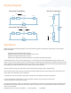
Piping Diagram
FILTER
VALVE 2VALVE 1
FLOW METER
VALVE 3
FLOW
BYPASS
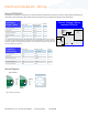
FILTER
VALVE 2VALVE 1
FLOW METER
VALVE 3
FLOW
BYPASS
FILTER
FILTER
VALVE 1
VALVE 2
FLOW METER
VALVE 3
FLOW
BYPASS
Horizontal Installation
Horizontal Two-Way Flow
Vertical Installation