an ISO 9001:2008 certified company is co nt Operational Manual in u High Resolution, Linearized Frequency Transmitters ed Models 294/269 D For Models 269-0XX-XXX 294-0XX-XXX 294-1XX-XXX
Table of Contents D is co nt in u ed General Description.................................... 3 Specifications..............................................4 Installation (269)......................................... 5 Installation (294)........................................ 6 High Temperature Operation................7-8 Additional technical documents regarding transmitter performance and advanced operation are available at: http://www.maxmachinery.com/ Max Machinery, Inc.
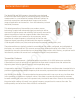
General Description ed The Model 294 and 269 frequency transmitters are designed an ISO 9001:2008 certified company to work with Max flow meters to provide extremely precise flow measurement in a cost effective package. Different options for electrical connections and temperature ranges cover a wide range of application environments – from the laboratory to harsh industrial processes.
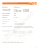
Transmitter Specifications Supply Voltage Supply Current 5-26 Vdc 25-30 mA typical Output (5.0 Volt Supply) (TTL and CMOS compatible) No Load 2.5K Load to Common 2.5K Load to +5 Volts Short Circuit Current (1) Output Impedance 45 mA 100 Ω Rise/Fall Time 0.
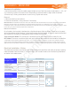
Installation - Model 269 Model 269 - Mechanical Installation Transmitters are installed on the meter at the factory. If a transmitter needs to be replaced in the ISO 9001:2008 certified company field, use the following anprocedure: ed 1. Disconnect wiring and remove the two socket cap screws to remove old transmitter. 2. Position alignment key on new transmitter with corresponding notch on the flow meter and drop into place. 3. Tighten both socket cap screws until snug.
Installation - Model 294 Mechanical Installation 1. Attach transmitter to the threaded magnet shield on top of the flow meter. Hand tighten. (~ 3 ft - lb)1 2. If necessary, loosen set screws on the transmitter’s cap and rotate to align cable as desired. an ISO 9001:2008 certified company 3. Ensure cap is firmly pushed down to seal O-ring. Tighten set screws. Removal 1. Remove electrical connections 2. Unscrew transmitter, using a wrench if necessary.
Rotation/Output Indicators The red/green rotational indicating LED (D2) will be illuminated when the circuit has power. One side will always be lit. The color will depend on where the meter stops in its rotation. The yellow signal LED’s illuminate only when the sensor output is “high”. Note: There are no selections or adjustments to be made on the circuit board. The only method of altering the setup parameters is through the Serial Interface Program.
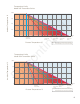
Temperature Limits Model 269 Transmitter Series 60 20 0 50 80 Standard model limit 100 150 170 ed 40 200 Hi temp model limit (24vdc) 210 Hi temp model limit (5vdc) in u Ambient Temperature °C 80°C 265 280 300° C Ultra Hi* temp model limit (5vdc) *Note: Ultra high temp model must be mounted with transmitter on side of the flow meter nt Process Temperature °C 250 Ultra Hi* temp model limit (24vdc) is 60 40 D Ambient Temperature °C 80°C co Temperature Limits Model 294 Transmi