an ISO 9001:2008 certified company Transmitter Interface Program Operational Manual Version 3.03.5 IH 290-100-350 • rev. 2/2012 • ©2012 Max Machinery, Inc.
an ISO 9001:2008 certified company Overview The transmitter interface software allows you to adjust configuration settings of your Max solid state transmitters. The following settings can be accessed and modified: Pulse Output Scaling, Analog Output Limits and Scaling, Signal Filtering Options and Compensation settings. To use the serial interface, an interface kit can be purchased from the factory (Max Part # 294-100-050).
an ISO 9001:2008 certified company Now you can complete the following steps to install the latest version of this program 1. Disable any automatic virus detection programs and exit all applications before running this installer. 2. Insert the MaxXmtr Serial Interface Program installation CD and follow the instructions on the screen. 3. If your PC has the AutoRun feature disabled, the SETUP.EXE program can be started from either Windows Explorer or by the following sequence: a.
an ISO 9001:2008 certified company 4. Select MaxXmtr from the start menu, or in Explorer launch MaxXmtr.exe from your installation directory. A dialog box will prompt the user to select the serial port. Choose the port to which you have connected the serial interface cable and press Continue. If the transmitter is not detected, an error message will be displayed. Verify that the transmitter is connected to the serial cable and powered up, then press Retry.
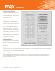
an ISO 9001:2008 certified company Output Data Screen The Output Data tab provides access to the most commonly adjusted parameters for the transmitter. Linearization On/Off This feature corrects for mechanical non-linearity of the meter to produce an output signal that is precisely proportional to flow. Typically the only reason to turn off linearization is to collect the calibration data with which to populate the linearization table on the factory data tab.
an ISO 9001:2008 certified company Flow Units This field shows the units used for collecting the linearization data. Analog Output This sets both the output limits and the output scaling. Voltage transmitters can be set anywhere between -10V and +10V, and current transmitters within the range of -20 mA to +20 mA. Because the transmitter receives a 2 stage calibration at the factory, it is possible to change the analog scaling at any time without loss of accuracy or need to re-calibrate.
an ISO 9001:2008 certified company Output Signal Dampening This feature sets the time constant/cut-off frequency used to filter the raw flow signal. Selecting zero will turn off the filtering completely. The zero setting can be useful if sudden flow changes need to be measured, or if filtering will be added after measuring the signal.
an ISO 9001:2008 certified company Factory Data Screen The Factory Data tab shows calibration settings that generally will only need to be set at the factory. Most fields are password protected. If needed, contact the factory for details. Compensation Options Compensation is a software feature where the transmitter measures the rotational speed of the meter thru one complete revolution, and then corrects for this variation.
an ISO 9001:2008 certified company Perform Factory The option is used only by the factory for initial compensation.