an ISO 9001:2008 certified company High Resolution, Linearized Frequency Transmitters Operational Manual For Models 269, 294 and 295
Table of Contents General description................................................................ 3 Transmitter specifications.................................................... 4 Installation - Model 269, 294............................................... 5 Installation - Model 295, 296............................................... 6 Electrical installation, wiring................................................ 6 High temperature operation................................................
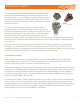
General Description Model 296 The Max frequency transmitters are designed to work with the entire family of Max Flow Meters provide an ISO 9001:2008to certified companyextremely precise flow measurement in a cost effective package. Different options for electrical connections and temperature ranges cover a wide range of application environments – from the laboratory to harsh industrial processes.
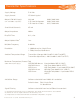
Transmitter Specifications Supply Voltage Supply Current 5-26 Vdc 25-30 mA typical Output (5.0 Volt Supply) (TTL and CMOS compatible) No Load 2.5K Load to Common 2.5K Load to +5 Volts Short Circuit Current (1) Output Impedance 45 mA 100 Ω Rise/Fall Time 0.
Installation - Model 269 Model 269 - Mechanical Installation Transmitters are installed on the meter at the factory. If a transmitter needs to be replaced in the ISO 9001:2008 certified company field, use the following anprocedure: 1. Disconnect the wiring and remove the two socket cap screws to remove the old transmitter. 2. Position the alignment key on the new transmitter with the corresponding notch on the flow meter and drop into place. 3. Tighten both socket cap screws until snug.
Installation - Model 295, 296 Model 295, 296 — Mechanical Installation 1. The transmitter is attached to the flow meter’s threaded magnet shield. Hand tighten only. (~ 3 ft-lb) 2. The transmitter lid has four thread paths. To realign the cable, remove the lid and rotate up to 180° an ISO 9001:2008 certified company and retighten using an alternate starting point. Tighten to compress the O-ring seal. Removal 1. Remove electrical connections 2. Unscrew transmitter, using a wrench if necessary.
Rotation/Output Indicators All of the microprocessor based transmitters incorporate a LED to indicate that they are producing a pulse output and/or detecting magnet rotation in the meter. An alternating red/green or blue/green LED indicates that the circuit is detecting a rotating magnet and should provide an output. Additional LED’s are present for setup, programming and troubleshooting and are not intended for general use. Note: There are no selections or adjustments to be made on the circuit board.
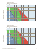
Temperature Limits Model 269 Transmitter Series Ambient Temperature °C 80 60 40 20 0 50 80 100 150 Standard temp model limit 170 200 Hi temp model limit (24Vdc) Process Temperature °C 210 Hi temp model limit (5Vdc) 250 265 Ultra Hi* temp model limit (24Vdc) 280 300 Ultra Hi* temp model limit (5Vdc) *Note: Ultra high temp model must be mounted with transmitter on side of the flow meter Temperature Limits Model 294 Transmitter Series Ambient Temperature °C 80 60 40 20 0 50 100
Temperature Limits Model 295 Transmitter Series 120 110 100 Ambient Temperature °C 80 60 40 One piece model limits Standard 2 part pickup High temp 2 part pickup 20 0 -25 50 100 110 (24Vdc) 125 (5Vdc) 150 155 200 225 250 300 225 250 300 Process Temperature °C Temperature Limits Model 296 Transmitter Series 120 110 100 Ambient Temperature °C 80 60 40 One piece model limits Standard 2 part pickup High temp 2 part pickup 20 0 -25 50 100 110 (24Vdc) 125 (5Vdc) 150 1
Installation - Hazardous Locations Applies only to Max Model EX295 and EX296 Transmitters with explosion proof certification. These transmitters provide protection via a flame proof housing and through current limiting to the an ISO 9001:2008 certified company circuit board: Must wire with a class 2 power supply (See table for loads).
Removal from Flow Meter Note: the transmitter does not need to be removed from the flow meter for any field servicing or adjustments. Normally, the flow meter and transmitter are shipped back to the factory for calibration as a unit. 1. Remove the locking screw at the edge of the lid and then remove the cap using a 3/8” socket drive. 2. Disconnect wires at the terminal block and remove wiring conduit from transmitter. 3. Locate the locking set screw below the conduit hole and remove it.
Electrical Requirements The device must be powered with a Class 2 power supply.
EC Declaration of Conformity We, Max Machinery Inc. declare as manufacturer under our sole responsibility that the product series 295/296 Explosion Proof Flow Transmitter is in conformity with the provisions of the European Community Directives as shown below. Applicable Series: Part numbers of the format 295-xx1-x00 and 296-xx1-x00 where ‘x’ does not affect conformity to the standards.