
Instruction Manual


3
IH 295-200-350 • rev. 6/2011 • ©2010-11 Max Machinery, Inc.
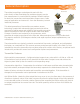
These Max transmitters are designed to work with the
entire family of Max Flow Meters to provide extremely precise
ow measurement in a cost effective package. Different options
for electrical connections and temperature ranges cover a wide
range of application environments – from the laboratory to harsh
industrial processes.
This latest generation of transmitters use modern sensor
technology coupled with advanced signal processing to deliver
new levels of performance and reliability. Hall sensors are used to
detect the position of a driven magnet inside a Max Flow Meter.
Changes in position are tracked by a microprocessor, which
generates an output proportional to the ow rate. Advanced signal processing provides both
ne angular resolution (0.36 degrees rotation) and rapid response (output updated every one
millisecond).
These transmitters are typically mated to a mechanical ow meter, congured, and calibrated at
the factory as a matched set. This ensures accuracy and allows quick setup in the eld. For eld
installations where the transmitter has not been setup with a meter at the factory, an optional serial
interface kit provides full access to all conguration options and parameters.
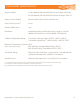
Transmitter Features
High resolution measurement - Congured output ranges to any valve within ± 10 Vdc or ± 20 mA.
Linearization of up to 16 points to fully describe the ow meter’s output curve and achieve the
highest system linearity over the meter’s entire operating range.
Compensation Algorithm – Compensates for variations in Hall sensor and ow meter characteristics
to provide a stable, undamped output that accurately represents the instantaneous ow rate. This
feature is factory set when the meter and transmitter are mated together. If the transmitter is
changed, the compensation can be performed via a button on the PCA.
Anti-Dither Buffer - Masks the false output that may occur at very low ow rates in the presence of
vibration or hydraulic noise. If the meter reverses direction the output signal will be interrupted for
a user selected portion of a meter rotation. Reverse ow exceeding the buffer setting will result in
an output proportional to reverse ow rate. The buffer quantity can be set from 1% to 100% of a
revolution.
an ISO 9001:2008 certified company
General Description
Ex Proof Model 295
Model 295
Model 296