
Instruction Manual


10
IH 295-200-350 • rev. 6/2011 • ©2010-11 Max Machinery, Inc.
Removal from Flow Meter
Note: the transmitter does not need to be removed from the ow meter for any eld servicing
or adjustments. Normally, the ow meter and transmitter are shipped back to the factory for
calibration as a unit.
1. Remove the locking screw at the edge of the lid and then remove the cap using a 3/8” socket drive.
2. Disconnect wires at the terminal block and remove wiring conduit from transmitter.
3. Locate the locking set screw below the conduit hole and remove it. Rotate the outer housing
clockwise until the screw hole lines up with a hole in the inner housing. Inserting an Allen key into
the threaded hole while rotating the housing can help in nding the point of alignment. Now re-
insert the set screw and hand-tighten it. This will lock the inner and outer housing together.
4. Unscrew the transmitter, using a strap wrench if necessary.
Moisture Protection
The housing is a liquid and vapor-tight enclosure certied to IP66. There is an O-ring seal at the
lid of the housing — the seal needs to be fully seated to provide moisture protection and achieve
ameproof specications.
About Explosion proof installations
For the Model 295 and 296 to fully adhere to the HazLoc certications, the wiring must meet the
appropriate codes.
(Use of a wire conduit does not make the installation explosion proof – read below.)
The transmitters which are certied for use in hazardous locations require the use of a 1/2” NPT
conduit tting. The wiring conduit must be sealed with a conduit stop within 18” of the device. If
you choose to use exposed cables, cable seals must be used with sealing ttings and the wiring must
be an approved armored cable. (For detailed information on the joint constructions used to achieve
a ame proof housing, please contact Max Machinery.)
Electrical Installation
Use wiring that is between 20 and 28 gauge and rated to at least 5°C above the maximum ambient
temperature, and rated to at least 80% of the maximum uid temperature.
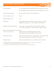
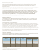
Pulse Output
Wiring
Circuit Board
Label
Mating
Cable Wire
Color**
Analog Output
Wiring
Two Part Transmitter
End Labels
Wire Color
Case ground Case Blue Case Com Brown
Common Com Black Com Rb Grey
Power* V+ Brown V+ Ra White
Signal Output (+) PHA White RET 5V Black
(Quad only) PHB Grey SIG Case Blue
* Consult Table
** (Color codes are typical for Max Machinery wired devices)