289 SERIES FLOW METER TRANSMITTERS
INSTRUCTION MANUAL 289 SERIES TRANSMITTER 289-763 Pickup Coil/Amplifier, Amphenol Connector 289-773 Pickup Coil/Amplifier, Weather-Tight, Explosion-Proof* TABLE OF CONTENTS General Description . . . . . . . . . . . . . . . . . . . . . . . . . . . .Pg 2 Specifications . . . . . . . . . . . . . . . . . . . . . . . . . . . . . . . . .Pg 3 Installation . . . . . . . . . . . . . . . . . . . . . . . . . . . . . . . . . . .Pg 4 User Options & Adjustments . . . . . . . . . . . . . . . . . . . . .
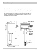
General Description The 289 Series Transmitter has an inductive pickup which senses the motion of an internal flow meter gear. As the tooth of a gear moves under the core of the pickup, a voltage is induced in a coil wound around the core. The gear is fastened to the rotor shaft of the 240 Series meter, which allows its rotational rate to be directly proportional to the flow rate. The output of the pickup coil is amplified and squared before being sent to the output terminals.
Specifications 289-763/773 5V Square Wave Output: Power Requirements: Voltage (5V regulator on PCA) . . . . . . . . . . . . . . . . . . . . .5-24VDC Nominal (3.5-30V Max) Current (No Load) Supply Voltage 3.5V 5.0 - 24.0V Operating 1.1mA 1.8mA Calibrating 1.6mA 3.0mA Output Signal Shape . . . . . . . . . . . . . . . . . . . . . . . . . . . . . . . . . . . . . .Square Wave Amplitude . . . . . . . . . . . . . . . . . . . . . . . . . . . . . . . . . . . . . . . . . .5V Rise and Fall Time . . . . . . . . .
Installation Mounting: The Model 289 transmitter screws on and off of the flow meter. Because of the random location of the starting point of the threads, one transmitter will probably not line up with the "in" and "out" ports of the flow meter like another will. The electrical outlet of the transmitter can be rotated one turn by loosening the clamping screw.
User Options & Adjustments 289-763/773 TRANSMITTER Grounding: S2-l connects Common and Case directly together. S2-2 connects Common and Case through 4.7 µF capacitors. By using either switch the effects of electrical noise on the transmitter can be reduced. If the system is not grounded at the indicator or if the flow meter is not physically grounded through its plumbing, use S2-l. If the system is grounded at the indicator, use S2-2.
Maximum Transmission Distance MAXIMUM TRANSMISSION DISTANCE The graph below shows typical conductor capacitance load vs. cable length for several types of cable. For instance, 1,000 ft. of 7 conductor #18 gauge stranded wire will put a 0.04 µF capacitive load on the output of the Model 289 transmitter. 289-760-350 © 1987 (Rev 5/06) Max Machinery, Inc.
Maximum Transmission Distance MAXIMUM TRANSMISSION DISTANCE (continued) The graph below provides the relationship between output capacitance loading and rise and fall time for the Model 289-763/773 output signal. For instance, with 0.4 µF the rise time of the Model 289 is about 89 µS, and the fall time about 45 µS. Consequently, the absolute maximum frequency the 289 could put out would be 1/(80 + 45) µS = 8000 Hz (frequency = 1/time). The signal would be a saw tooth pattern.
Typical K-Factors / Typical Connections Typical K-Factors for 240 Series Flow Meters using the 289 Series Transmitter 241 Flow Meter (.062 Liter/Rev) Pulses/Liter . . . . . . . . . . . . . . . . . . . . . . . . . . . . . . . . . . . . . . . . . . . . . . .403 Maximum Rate . . . . . . . . . . . . . . . . . . . . . . . . . . . . . . . . . . . . . . .190 L/min 242 Flow Meter (.182 Liter/Rev) Pulses/Liter . . . . . . . . . . . . . . . . . . . . . . . . . . . . . . . . . . . . . . . . . . . . . . .