
Instruction Manual
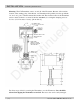
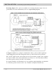


Zero Adjustment: R52 (276-515/276-525) R64 (276-517/276-527) Adjust the output current
to 4.000mA with zero flow through the Flowmeter.
Span Adjustment: S1 Coarse Range and R35 or R47 Fine Span Adjustment. Table I lists the
approximate volumetric displacements of flow meters that can be used with the 276
transmitters. Use this table to calculate the RPM of the flow meter at maximum flow.
TABLE I.
METER MAXIMUM FLOW AND DISPLACEMENT
FLOWMETER MAXIMUM FLOW DISPLACEMENT PER REVOLUTION
CC/MIN GAL/MIN CC GALLONS
213 1,800 0.48 0.870 .00023
214 10,000 2.64 10.5 .00285
215 40,000 10.6 47.6 .0128
216 100,000 26.4 169.5 .0446
220 10,000 2.64 9.12 .0024
221 55,000 14.5 23.5 .0062
222 75,000 19.8 47.4 .0125
241 189,000 50.0 62.1 .0164
251 189,000 50.0 62.1 .0164
242 540,000 143.0 182.0 .0480
243 1,400,000 370.0 574.0 .152
244 3,500,000 925.0 1700.0 .456
245 8,000,000 2114.0 6060.0 1.60
(FOR EXAMPLE: THE 213 MAX RPM IS: 1800 CC/MIN ÷ 0.870 CC/REV = 2069 RPM.)
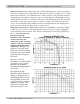
Table II lists the RPM range of each Range Switch setting for both 276 transmitters. Use this
table to estimate the correct range position.
TABLE II.
RPM RANGE VS SWITCH POSITION (RPM AT 20mA OUT)
2 7 6 - 5 X 5 2 7 6 - 5 X 7
SWITCH MAX MIN MAX MIN
POSITION GAIN GAIN GAIN GAIN
1 1294 3620 1290 3612
2 568 1589 549 1537
3 249 697 233.6 654
4 109 306 99.4 278.3
5 48 134 42.3 118.4
6 21 59 18 50.4
276-515-350 © 2006 Max Machinery, Inc. ( 7 )
USER OPTIONS & ADJUSTMENTS
—Zero & Span Adjustments
Discontinued