
Instruction Manual
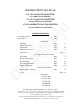
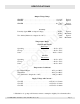
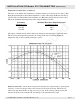
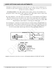
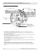
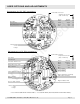
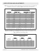

Table I list the approximate volumetric displacements of flow meters that can be used with the 272
transmitters. Use this table to calculate the RPM of the flowmeter at maximum flow.
TABLE 1: METER MAXIMUM FLOW AND DISPLACEMENT
FLOWMETER MAXIMUM FLOW DISPLACEMENT PER REVOLUTION
MODEL CC/MIN GAL/MIN CC GALLONS
213 1,800 0.48 0.870 .00023
214 10,000 2.64 10.5 .00285
215 40,000 10.6 47.6 .0128
216 100,000 26.4 169.5 .0446
220 10,000 2.64 9.12 .0024
221 55,000 14.5 23.5 .0062
222 75,000 19.8 47.4 .0125
241 189,000 50.0 62.1 .0164
251 189,000 50.0 62.1 .0164
242 540,000 143.0 182.0 .0480
243 1,400,000 370.0 574.0 .152
244 3,500,000 925.0 1700.0 .456
245 8,000,000 2114.0 6060.0 1.60
FOR EXAMPLE: THE MODEL 213 MAXIMUM RPM IS: 1800 CC/MIN ÷ 0.870 CC/REV = 2069 RPM.
Table II list the RPM range of each Range Switch setting for all three 272 transmitters. Use this
table to estimate the correct range position.
TABLE 2: RPM RANGE VS SWITCH POSITION
(RPM AT 10V OUT)
272-5X5 272-5X7 272-5X8
SWITCH MAX MIN MAX MIN MAX MIN
POSITION GAIN GAIN GAIN GAIN GAIN GAIN
1 1985 5559 2197 6157 1985 5559
2 794 2224 879 2460 794 2224
3 318 889 351 984 318 889
4 127 356 141 394 127 356
5 51 142 36.3 117 51 142
6 20.3 57 21 53 20.3 57
Page 10 272-500-350 © 1996 (Rev. 8/00) Max Machinery, Inc.
USER OPTIONS AND ADJUSTMENTS
Discontinued