
Manual

( 9 ) 234-000-350 © 2005 Max Machinery, Inc.
234-000-350 © 2005 Max Machinery, Inc. ( 9 )
Electronic Installation
When to Calibrate
Calibration should be performed under the following conditions:
1. If the circuit board of the transmitter is changed.
2. If the connector between the pickup coils and the circuit board is reversed.
3. If it is suspected that the output signal contains more frequency modulation than it should have. (i.e.: Pulse
widths vary by more than ±15%, and variations are not random, but cyclical at 4 times per revolution)
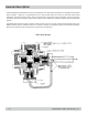
Calibration Procedure
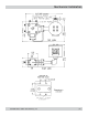
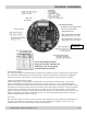
1. Set up a steady flow rate through the meter that results in a meter rpm between 20 and 500, ideally
somewhere around 100 rpm. The position indication LED’s in the center of the circuit board can aid in rpm
determination (i.e.: at 100 rpm, each light will blink 10 times in 6 seconds).
2. Rotate S3 to the ‘0’ position to enable calibration.
3. Press the ‘CAL’ button, S5. If the ‘SLOW’ LED (D8) comes on, wait 10 seconds for it to go off, increase the
flow rate and try pressing the ‘CAL’ button again.
4. Wait for the ‘CAL’ LED (D9) to stop blinking and turn back off. While the calibration is active, the position
indication LED’s in the center of the board will pause. As soon as the calibration is complete, they will resume
activity.
5. The calibration is now complete. Return S3 to the appropriate setting to get the desired number of output
pulses per revolution.