
Manual

( 8 ) 234-000-350 © 2005 Max Machinery, Inc.
Electronic Installation
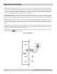
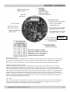
‘SLOW’ LED:
D8: If a calibration is initiated but the flow rate is too low to give acceptable results, the calibration will be
aborted, and this LED will light up red for 10 seconds. See Calibration Section for more information on
calibration procedures.
‘MEMORY FAIL’ LED:
D7: The microprocessor continually checks the integrity of its program storage memory. If one or more memory
values do not read what they are supposed to, this LED will turn on. Two possible causes of memory failure are
prolonged operation/storage at temperatures exceeding the ratings and transient voltages applied to inputs and/
or outputs that exceed ratings. If the transmitter does not appear to be functioning correctly and this LED is on,
the unit should be sent back to the factory for service.
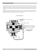
The coils of the Model 234 stators and the printed circuit board need to be calibrated as a set. The calibration
procedure initiates a routine that determines the offsets needed to balance the output signals from the coils.
When used with a piston flow meter, the calibration procedure includes an additional routine that measures the
linear position of the stator with respect to the meter. This allows the transmitter to compensate for cyclical
variations in rotational velocity of the meter, resulting in a steady output frequency.
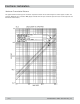
The recommended flow range for calibration is that which will turn the meter at 20-500 rpm. Lower flow rates
(resulting in rotor speeds below 20 RPM) will cause the ‘SLOW’ LED to come on and the calibration will not take
place. Successful calibration will occur at higher flow rates (rotor speeds above 500 RPM) but the results may
not be as good as those which would be obtained at a lower flow rate. A flow rate resulting in a flow meter
rotation of 100 rpm will give good calibration results.
When doing a calibration on a piston meter, it is critical that the flow rate remains constant (less than 10%
variation) for the routine that determines the linear position to be successful. When a steady flow passes
through a four-piston meter, the meter speeds up and slows down 4 times per revolution. The phase of this
cyclic speed variation is determined during calibration by finding the position of the 4 speed peaks in a
revolution. These speed peak locations are measured for 8 revolutions (32 peaks), then run through an
averaging procedure. Once this is done, the tachometer can internally compensate for the speed variations to
output a steady frequency under steady flow conditions.
Error can be introduced into this phasing procedure if the system flow rate is pulsating (i.e.: driven by a piston
pump). If there are peaks in the flow rate that overshadow the speed peaks due to the 4-piston geometry, the
calibration routine will incorrectly determine the phase of the cyclic speed variation and will subsequently apply
the compensation out of phase.
The phase balancing routine that occurs for all types of meters requires 16 revolutions of the meter to reach
completion. The ‘CAL’ LED changes color (red to green or green to red) 4 times per revolution, or 64 blinks for
the entire calibration. The linear position determination (phasing) requires 8 revolutions, so the ‘CAL’ LED will
blink an additional 32 times after the 64 phase balancing blinks when calibration is performed on a piston meter.
If the flow is stopped part way through a calibration, the blinking will stop and the calibration will not reach
completion since it requires a fixed number of meter revolutions. In such a case, a new calibration should be
done at a steady flow rate.