
Manual


( 7 ) 234-000-350 © 2005 Max Machinery, Inc.
234-000-350 © 2005 Max Machinery, Inc. ( 7 )
Electronic Installation
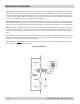
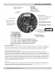
Microprocessor Reset:
S2: In the event that the tachometer does not appear to be operating correctly, resetting the microprocessor
by momentarily depressing S2 may solve the problem. While the reset button is depressed, the ‘MEM FAIL’
LED will turn on, and if the memory is good, the LED should turn back off when the button is released.
LVDT Rotor Position Indication LED’s:
D3-D6: These LED’s provide a graphical representation of the position of the LVDT slugs. This can be a
helpful troubleshooting aid when trying to determine if a meter is turning or not. The rotational pattern
observed on the LED’s corresponds directly to the speed of the LVDT slugs. At high speeds, the LED’s will just
look like they are blinking; the human eye can no longer discern the direction of motion. At very high speeds
the blinking will not even be obvious and they will all appear to be a constant brightness. At these higher
speeds, a divide-by-ten feature can be activated by pressing S5 (the ‘CAL’ button, make sure S3 is not in the 0
position, otherwise the calibration routine will be run!). This only slows down the Rotor Position indication
LEDs, the output frequency does not change.
‘CAL’ LED:
D9: This LED changes color (red to green or green to red) 4 times per revolution while the microprocessor is
performing the calibration routine on the stator coils. When calibration is complete, it will turn off. See
Calibration Section for more information on calibration procedures
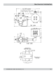
Due to the single sine wave
output of the LVDT encoder, the
resolution is 1/2 of the values
screenprinted on the PCB.
234 Series also
use 220/240
4.5-24