
Manual

( 6 ) 234-000-350 © 2005 Max Machinery, Inc.
Electronic Installation
Environment: The transmitter housing should be kept as cool as possible due to the temperature limits of the
electronic components. If the ambient temperature rises above 130
0
F (55
0
C), the maximum fluid temperature at
the flow meter will have to be derated.
The weather-tight versions of the flow meter require that the electrical conduit connection be sealed with pipe
dope or a potting fitting. If this precaution is not taken, moisture may form inside the transmitter housing,
resulting in inaccurate readings or circuit failure. The amphenol connector versions of the Model 234 offer
moderate protection from moisture and dust, but are not totally sealed.
Grounding: Two dip switches are provided. The Ground Switch S1-1, when activated, connects the circuit common
to the case terminal. The Filter Switch S1-2 connects common to case through two back to back electrolytic
capacitors. These two switches facilitate system grounding procedures which will reduce electrical noise problems.
It is advisable to have the common of any system physically grounded at one point only. If your system is grounded
at the receiving or indicator end, then it is not advisable to also ground it at the transmitter end. This may cause
a ground loop. In this case, it is advantageous to connect the circuit common to case via the capacitors (filter).
This will give some extra immunity to electrical noise.
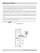
Interconnections: The cable connection to the Model 234 should be made with shielded cable, with the shield
itself connected only at the receiving end. The transmitter output stage is designed to drive up to 1000 feet (300
m.) of cable without problems. Even longer lengths may prove feasible depending on such factors as external
electromoagnetic interference and the sensitivity of the receiving indicator.
K-Factors: Each Model 234 Flow Meter is supplied with a calibration sheet showing the actual number of pulses
output per cubic centimeter (or other engineering unit) of metered fluid at several different flow rates. These
numbers are termed “K-Factors”. The individual or average K-Factor is used to calibrate the receiving indicator for
the proper display in the desired engineering units.
Reverse Flow Buffer: The transmitter square wave signal employs a reverse flow buffer designed to eliminate
false ouputs when the flow meter is subjected to hydraulic or mechanical oscillations with no actual net flow. Flow
through the meter must total 1/2 of a revolution (approx. 5.4 cc) before a pulse is output in either the forward or
reverse direction. At low flows, a noticeable period of time will be required to fill up this buffer. For instance, at 20
cc/min, 15 seconds will elapse before an output signal is observed.
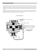
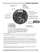
Two-Phase or Square Wave Select:
S4-2: Depress side that corresponds to desired output. ‘2PH’ gives a 2-phase quadrature output with the two
phases separated by 90° (Ph A on Terminal 5 and Ph B on Terminal 6). The ‘COMB OUT’ setting gives a single
square wave output that combines the information in the two
phases into a single output of double the frequency (Combined
Output on Terminal 4, Direction on Terminal 6). If S4-2 is set
wrong, an unexpected output signal will result since the same
output circuitry is used for the two distinct output options.
Output Frequency Select:
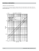
S3: Rotary switch allows selection of output resolutions of 16 to 500 pulses per revolution (square wave output),
or 8 to 250 pulses per revolution (per phase) if the 2-phase output option is selected. The resolution can be
changed while the tachometer is operating, and the new value will take effect immediately. Please Note: The
screen printed resolution on the circuit board applies to 210/220/240 Series meters. See table for resolution.
Output Indicators:
D10, D11: These bi-color (red, green) LEDs indicate the status of the outputs. If the 2-phase output mode has
been selected, the state of Phase A and Phase B are each shown on the corresponding LEDs (‘OUT/∅A’ and
‘DIR/∅B’). If the combined output mode has been selected, the LED labeled ‘OUT/∅A’ shows the status of the
pulse output channel, and the LED labeled ‘DIR/∅B’ indicates the direction.