
Manual

Mechanical Installation
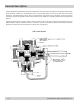
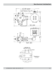
Orientation: The Model 234 is internally ported to allow air to be fully expelled from the meter provided the fluid
enters from the bottom (as shown below). Air in the system can cause response delays and errors in measurement.
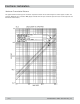
If the meter has to be mounted 90 degrees from what is shown, accuracy at low flows (less than flow rate in cc’s
x viscosity in centipoise = 200) may be affected. This is due to the weight of the piston assembly adding slightly
to the pressure drop required to lift the assembly during operation.
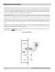
Line and Bypass Valves: These valves allow filter cleaning or flow meter removal without completely shutting
the system down and draining the lines. They also allow system start-up under conditions which could damage the
meter, such as air in the lines (which can overspeed the meter), high temperature conditions or initial line surges.
Filtration: The meter cannot tolerate contamination such as Teflon® tape, broken pipe threads, welding slag, sand
or other particulate matter. In general, a 10 micron filter is recommended, although in some applications finer
filtration may be worthwhile. If bidirectional flow is used, a filter should be installed on both sides of the flow
meter.
When the fluid contains large amounts of soft materials, it may pass through the meter satisfactorily but tend to
clog the filter. In this case, the filter may not be appropriate. A Max Sales or Technical Service Engineer can be
consulted for information regarding specific materials.
Clean Plumbing: Before installing the flow meter, clean the inside of the pipe line with compressed air or steam.
This is particularly important with new pipe.
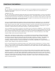
Typical Installation
( 4 ) 234-000-350 © 2005 Max Machinery, Inc.